Subsea electrical penetrator
a technology of electrical penetrators and subsea water, which is applied in the direction of electrically conductive connections, coupling device connections, electrical apparatus, etc., can solve the problems that the mechanical seals of the penetrator b>10/b> do not always provide a watertight seal
- Summary
- Abstract
- Description
- Claims
- Application Information
AI Technical Summary
Problems solved by technology
Method used
Image
Examples
second embodiment
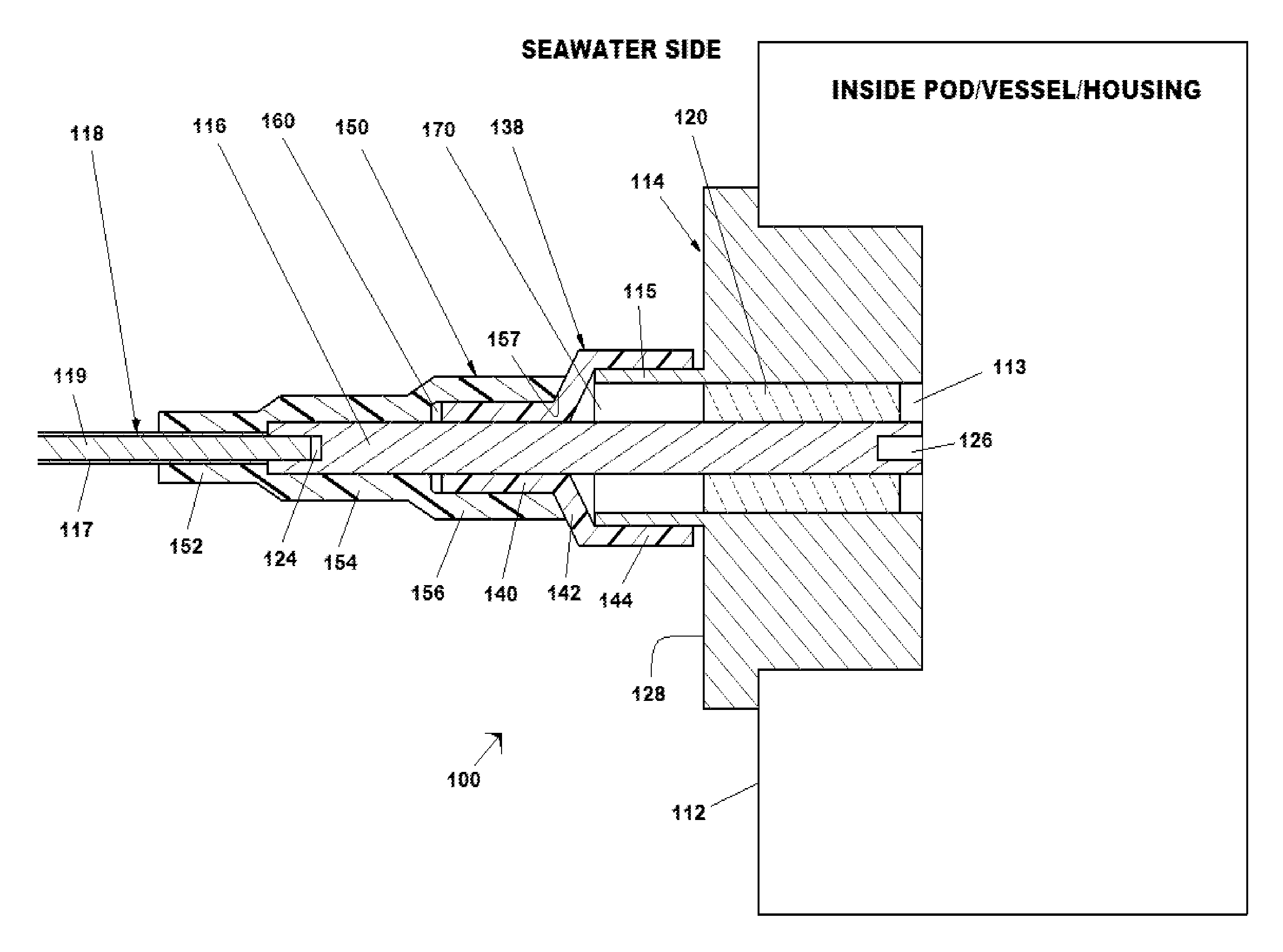
[0038]A subsea penetrator according to the invention is shown in FIG. 3. In this embodiment penetrator 200 has an annular recess 280 in face 228 of body 214 in lieu of cylindrical projection 115. Annular recess 280 may be concentric with central axial bore 213. This embodiment provides increased protection against mechanical damage to the surface of penetrator body 214 engaged by section 244 of inner boot seal 238. Inner boot seal 238 is comprised of three sections—smaller diameter section 240 is sized to fit in watertight engagement with pin 216; larger diameter section 244 is configured to engage the inner wall of annular recess 280 in a watertight manner; and, transition section 242 connects sections 240 and 244.
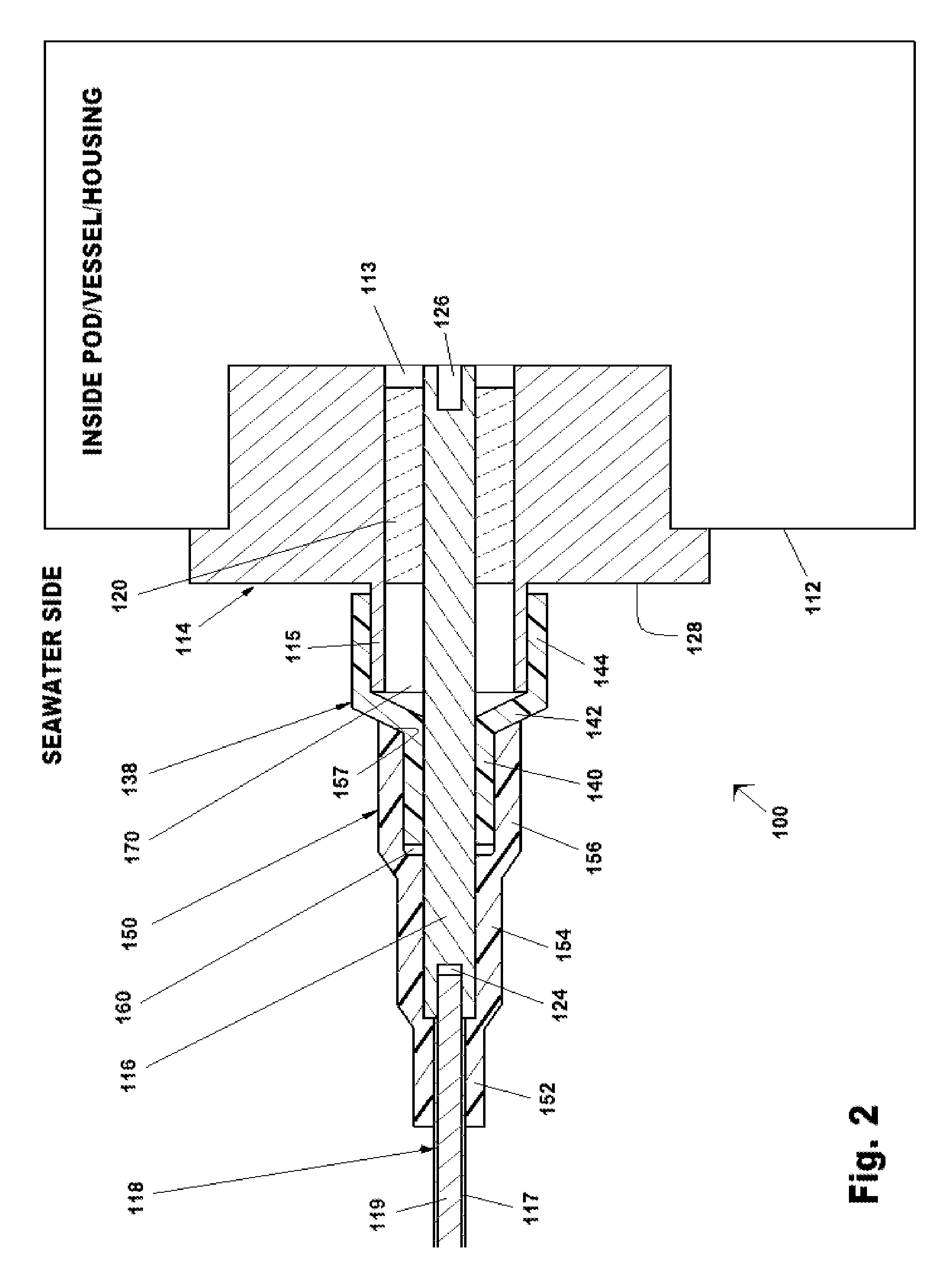
[0039]Elements of this embodiment that otherwise correspond to those of the embodiment illustrated in FIG. 2 are designated with reference numbers which differ by 100 from those in FIG. 2.
[0040]A penetrator 200 according to this second embodiment of the invention may be f...
third embodiment
[0041]A subsea penetrator according to the invention is shown in FIG. 4. In this embodiment penetrator 300 has a single boot seal but, unlike the penetrators of the prior art, penetrator 300 comprises oil-filled volume 370 which may act as a pressure compensator ensuring that little or no differential pressure exists between the surrounding seawater and the junction between connector pin 316 and boot seal 330.
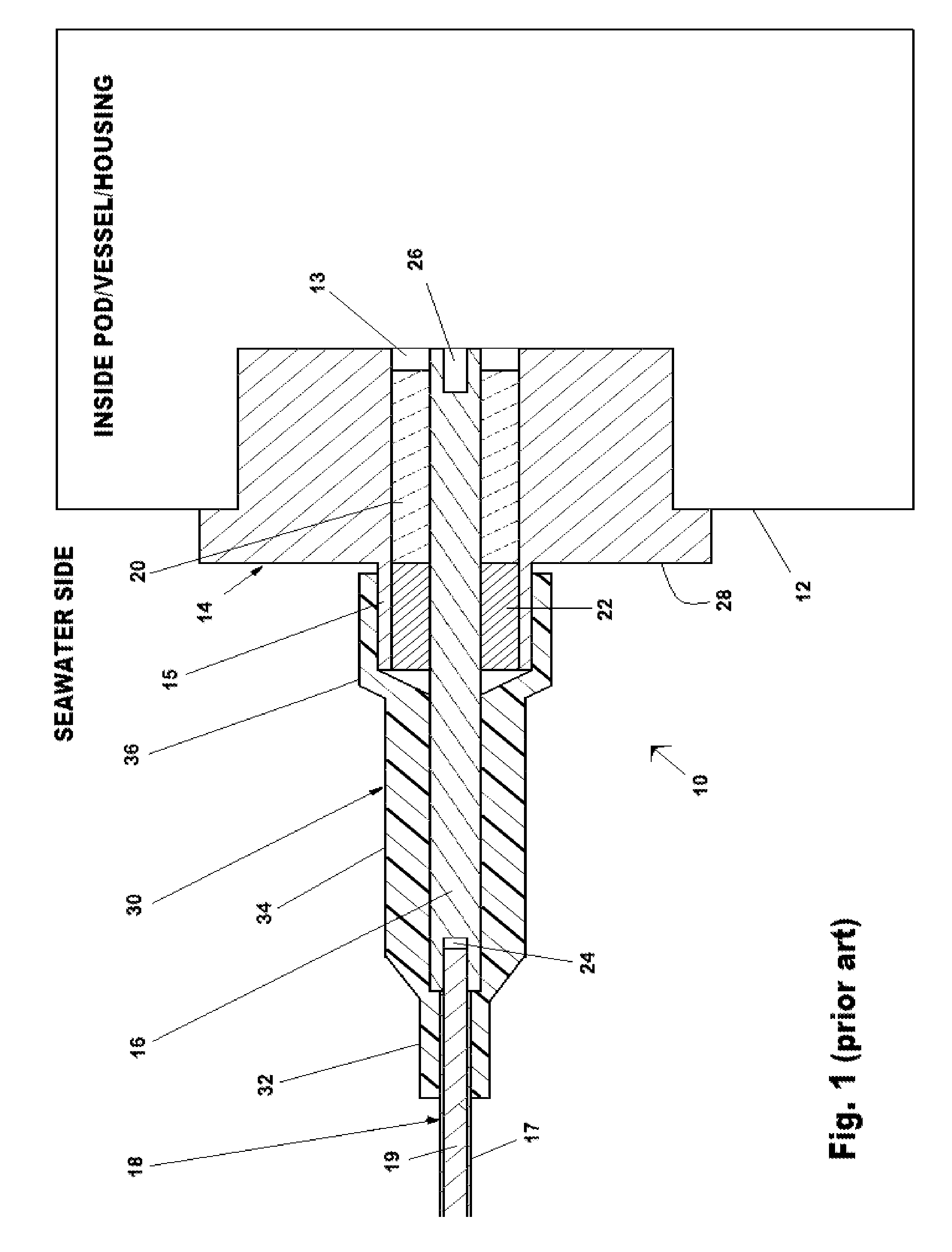
[0042]Boot seal 330 of prior art penetrator 300 is comprised of outer section 332, which engages jacket 317 of cable 318, middle section 334, which seals to the outer surface of connector pin 316, and inner section 336 which engages the outer wall of projection 315. Ideally, each of these engagements provides a watertight seal. It will be appreciated by those skilled in the art that a penetrator according to the embodiment illustrated in FIG. 3 may similarly be configured with a single boot seal.
[0043]Elements of this embodiment that otherwise correspond to those of the embodim...
PUM
 Abstract
Description
Claims
Application Information
 - R&D
- Intellectual Property
- Life Sciences
- Materials
- Tech Scout
- Unparalleled Data Quality
- Higher Quality Content
- 60% Fewer Hallucinations
Browse by: Latest US Patents, China's latest patents, Technical Efficacy Thesaurus, Application Domain, Technology Topic, Popular Technical Reports.
© 2025 PatSnap. All rights reserved.Legal|Privacy policy|Modern Slavery Act Transparency Statement|Sitemap|About US| Contact US: help@patsnap.com


