Surgical retractor device and method of use

a retractor device and retractor technology, applied in the field of surgical retractor devices, can solve the problems of unsuitable laparoscopic applications, inability to dissect and/or coagulate the transected, and the retractor device disclosed in scott, etc., and achieve the effect of maintaining substantially constant biasing or traction for

Inactive Publication Date: 2010-04-06
BOSTON SCI SCIMED INC
View PDF15 Cites 13 Cited by
  • Summary
  • Abstract
  • Description
  • Claims
  • Application Information

AI Technical Summary

Benefits of technology

[0014]In one preferred embodiment, each retracting member applies a substantially uniform biasing force during retraction of the tissue. Consequently, as additional tissue is resected, the biasing or traction force remains substantially constant. In this regard, there is no need to reposition the retracting members to apply a larger traction force to compensate for any slack in the system. The spring-biased rotatable member rapidly accommodates any slack that builds in the system as the resection operation proceeds.

Problems solved by technology

Unfortunately, using the technique disclosed in Aloia et al., a single surgeon cannot dissect and / or coagulate the transected tissue while at the same time applying the necessary traction to the stay sutures to expose the deepening transaction plane.
The retraction device disclosed in Scott, however, is unsuitable for laparoscopic applications.

Method used


Image

  • Surgical retractor device and method of use
  • Surgical retractor device and method of use
  • Surgical retractor device and method of use

Examples


Embodiment Construction

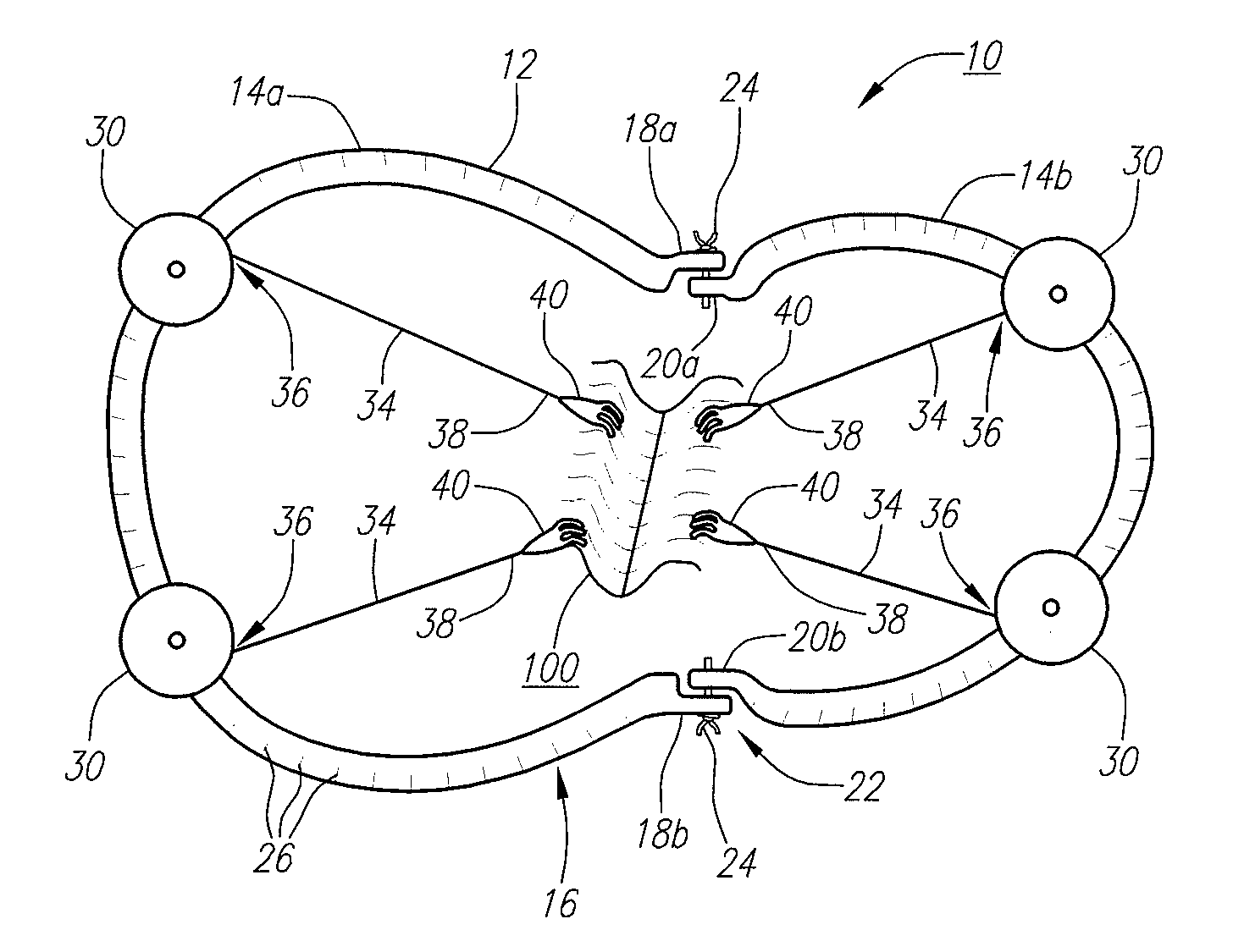
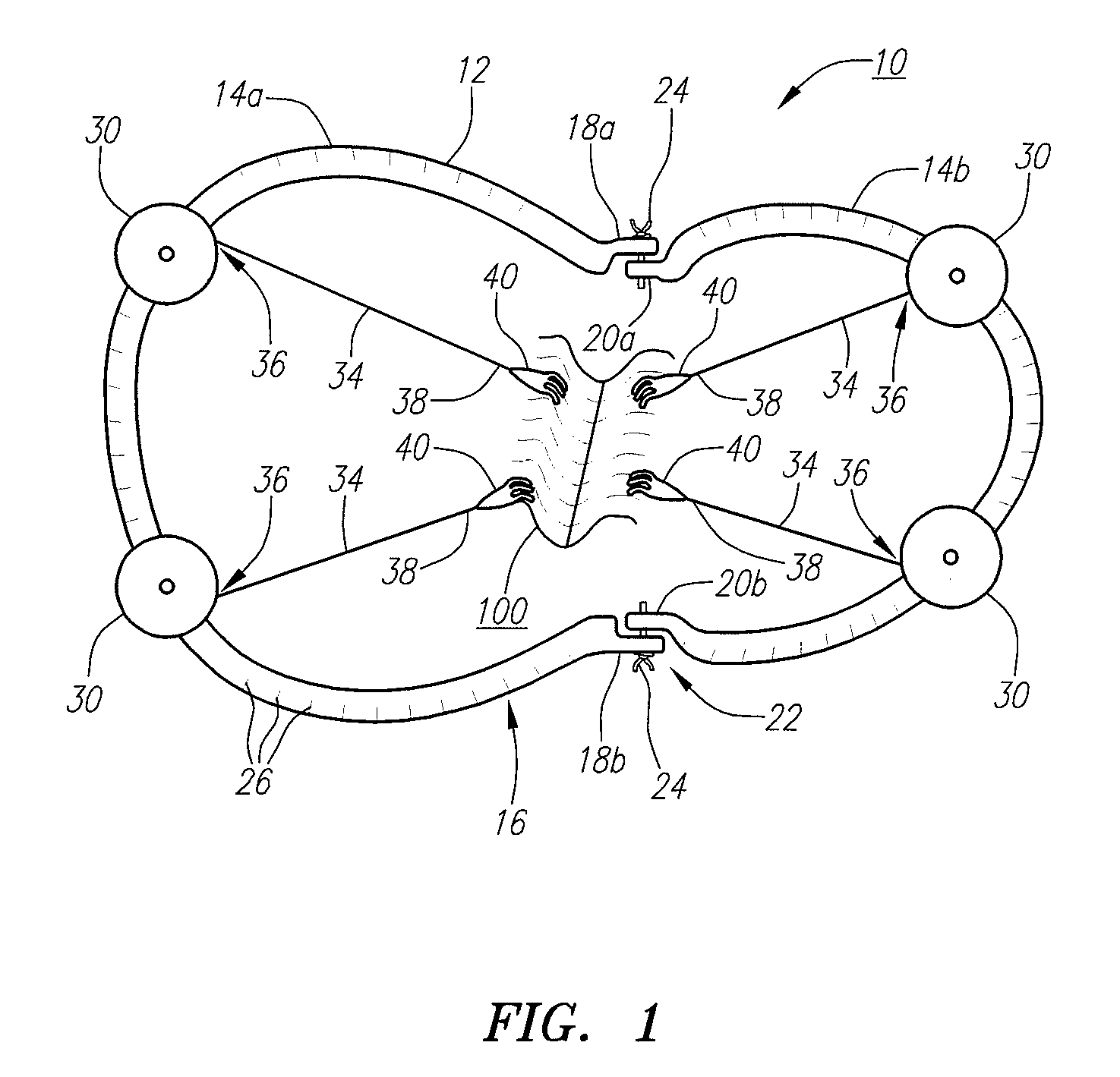
[0028]FIG. 1 illustrates a surgical retractor device 10 according to one embodiment. The surgical retractor device 10 includes a frame 12 which may be formed as a single piece or, alternatively, as shown in FIG. 1, is formed from multiple sub-frames 14a, 14b. The frame 12 defines an outer periphery 16 that generally surrounds a region of tissue 100 that is to be operated on.

[0029]The frame 12 in FIG. 1 includes a first sub-frame portion 14a that is generally arcuate or rounded and terminates in ends 18a, 18b. The frame 12 also includes a second sub-frame portion 14b that has a similar shape and terminates in ends 20a, 20b. The second-sub frame portion 14b may be dimensioned such that it can nest within the larger sub-frame portion 14a when in a collapsed configuration (described in more detail below). The first and second sub-frame portions 14a, 14b are connected to one another via a pivot point22. In one embodiment, bolts 24 or other adjustment members are used to secure the two su...


PUM


Abstract

A surgical retractor device includes a frame and at least one retracting member configured for being secured to the collapsible frame. The retracting member is formed from a spring-biased rotatable member, a tension line secured at a proximal end to the spring-biased rotatable member, and a tissue securing member disposed at a distal end of the tension line. In certain embodiments, the surgical retractor may be collapsible and delivered laparoscopically to the resection site.

Description

FIELD OF THE INVENTION[0001]The field of the invention generally relates to surgical retractor devices. More particularly, the field of the invention pertains to surgical retractor devices capable of imparting a biasing force to a portion of tissue. In certain embodiments, the device may be administered laparoscopically.BACKGROUND OF THE INVENTION[0002]During many surgical procedures, a region of tissue such as an organ is cut or resected by the operating physician. In order to more fully expose a cutting or resection plane, it is known to retract or pull apart the cut tissue. For instance, one or more stay sutures may be secured to the tissue and the sutures may be pulled taught to open or expose the deepening resection plane. As one illustrative example, one known method of performing hepatic parenchymal transaction utilizes polypropylene stay sutures to expose the deepening transaction plane.[0003]The details of this operative technique are disclosed in Aloia et al., Two-Surgeon ...

Claims


Application Information

Patent Timeline
Patent Type & Authority Patents(United States)
IPC IPC(8): A61B1/32
CPCA61B17/0293A61B17/0206A61B2017/0287A61B17/0218
Inventor RIOUX, ROBERT F.BURO, DINO D.
Owner BOSTON SCI SCIMED INC
Why Eureka
Try Eureka