
Organic Electroluminescent Device Allowing Adjustment of Chromaticity

a chromaticity adjustment and electroluminescent technology, applied in the direction of electroluminescent light sources, static indicating devices, instruments, etc., to achieve the effect of keeping the luminescence brightness almost constan

Inactive Publication Date: 2008-08-07
UDC IRELAND
View PDF8 Cites 51 Cited by
  • Summary
  • Abstract
  • Description
  • Claims
  • Application Information

AI Technical Summary

Benefits of technology

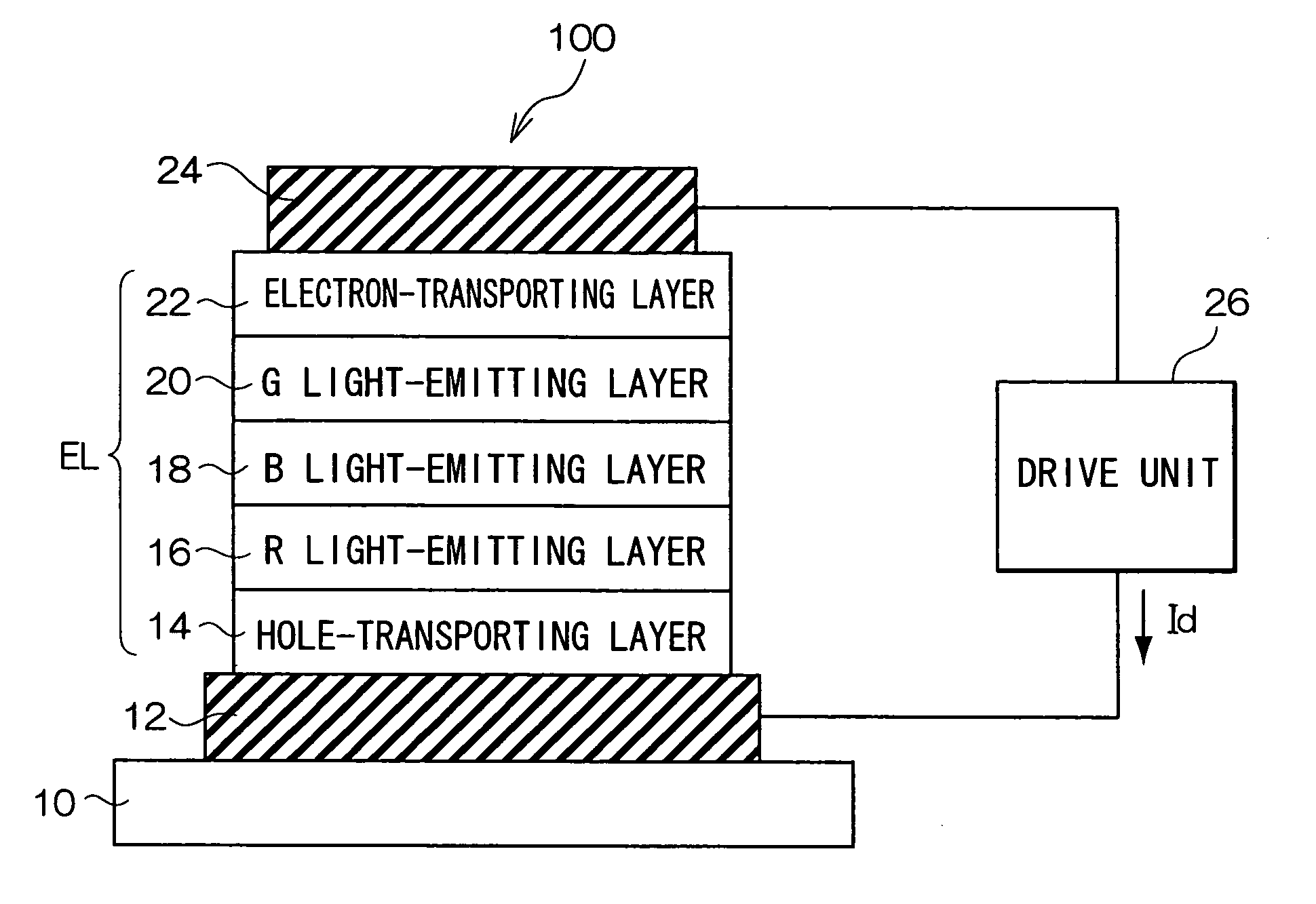
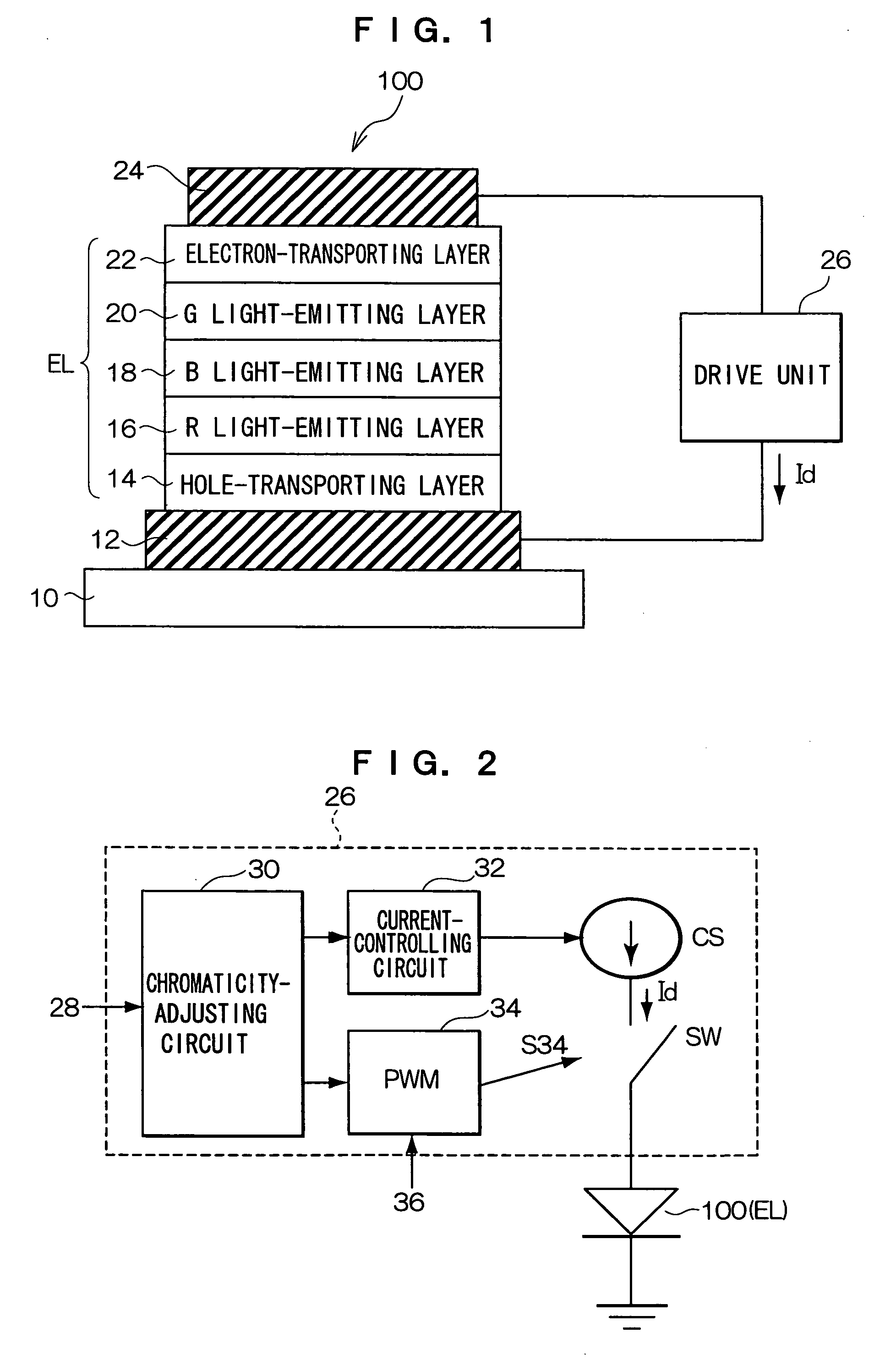
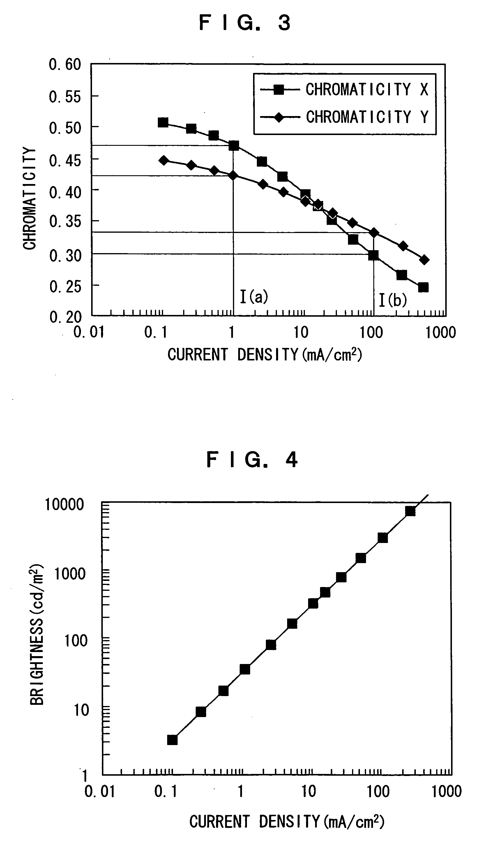
[0008]The above aspect provides an organic electroluminescent device that can adjust the emission chromaticity to a value corresponding to the chromaticity adjustment input by controlling the drive current to the organic light-emitting element in response to a chromaticity adjustment input for adjustment of emission chromaticity, keep the luminescence brightness almost constant by adjusting the current-applying period per unit of time according to the control of the drive current, and adjust the emission chromaticity to a desirable value without alteration of luminescence brightness. The organic electroluminescent device can be used as a lighting device or a backlight for liquid crystal display devices. The organic electroluminescent device can also be used as an emission segment in segment display devices.

Problems solved by technology

However, in the prior arts, Non-patent Documents 1 and 2 and Patent Document 1, there is no description on the lighting or display device using white luminescence that can adjust its chromaticity while keeping its luminescence brightness at a constant level.

Method used


Image

  • Organic Electroluminescent Device Allowing Adjustment of Chromaticity
  • Organic Electroluminescent Device Allowing Adjustment of Chromaticity
  • Organic Electroluminescent Device Allowing Adjustment of Chromaticity

Examples


first example

[0037]FIG. 6 is a chart showing the configuration of the organic EL device in the first example. The organic EL element in this example has an organic EL layer consisting of a hole-injecting layer 14A, a hole-transporting layer 14B, a red light-emitting layer 16, a blue light-emitting layer 18, a hole-blocking layer 40, and an electron-transporting and green light-emitting layer 42. The structure is prepared in the following way:

[0038]First, a glass substrate 10 carrying an ITO electrode 12 previously formed thereon is ultrasonicated and cleaned in water, acetone, and isopropyl alcohol, and treated with far ultraviolet ray (UV) and ozone; then, in a vacuum evaporator (1×10⁻⁶ torr, substrate temperature: room temperature), 2-TNATA (4,4′,4″-tris(2-naphthylphenylamino) triphenylamine) is deposited thereon as the hole-injecting layer 14A to a thickness of 140 nm, then α-NPD (N,N′-dinaphthyl-N,N′-diphenyl-[1,1′-biphenyl]-4,4′-diamine) is deposited thereon as the hole-transporting layer 1...

second example

[0041]FIG. 7 is a chart showing the configuration of the organic EL device in the second example. The organic EL element in this example has an organic EL layer consisting of a hole-injecting layer 14A, a hole-transporting layer 14B, a red and blue light-emitting layer 44, a hole-blocking layer 40, and an electron-transporting and green light-emitting layer 42. The structure is prepared in the following way:

[0042]First, a glass substrate 10 carrying an ITO electrode formed thereon is ultrasonicated and cleaned in water, acetone, and isopropyl alcohol and treated with UV and ozone; in a vacuum evaporator (1×10⁻⁶ torr, substrate temperature: room temperature), 2-TNATA is deposited thereon to a thickness of 140 nm so as to form the hole-injecting layer 14A, and α-NPD is deposited thereon to form the hole-transporting layer 14B to a thickness of 10 nm. A layer of a blue guest material t(bp)py, a red guest material DCJTB, and a host material CBP codeposited (vapor deposition ratio t(bp)p...


PUM


Abstract

An object of the invention is to provide an organic electroluminescent device emitting a light at an emission chromaticity properly adjusted while the luminescence brightness is kept constant. The organic electroluminescent device according to the invention, has an organic electroluminescence element having electrodes and an organic electroluminescent layer emitting white light at a chromaticity corresponding to the drive current density formed between the electrodes, and a drive unit driving the organic electroluminescence element while supplying current and controlling the drive current and the current-applying period per unit time in response to chromaticity adjustment input. And, the drive unit controls the drive current to be a first current and the current-applying period to be a first period respectively in response to a first chromaticity adjustment input, and controls the drive current to be a second current larger than the first current and the current-applying period to be a second period shorter than the first period respectively in response to a second chromaticity adjustment input, and adjusts the emission chromaticity of the light emitted while the luminescence brightness of the organic electroluminescence element is kept almost constant. In this way, in response to the chromaticity adjustment input for adjusting emission chromaticity, it is possible to adjust the emission chromaticity corresponding to the chromaticity adjustment input by controlling the drive current to the organic light-emitting element while keeping the luminescence brightness almost constant by adjusting the current-applying period per unit time according to the control of the drive current, thereby the light emission is adjusted to a desired emission chromaticity without change in luminescence brightness.

Description

TECHNICAL FIELD[0001]The invention relates to an organic electroluminescent device and in particular, to an organic electroluminescent device with white luminescence allowing the chromaticity arrangement while preserving its white brightness.RELATED ART[0002]Organic electroluminescence (EL) elements, which emit light on their own (selfluminous light) by current driving and respond rapidly to current driving (high speed response), have a potential for application to flat panel display devices. On the other hand, organic EL elements are also thin and light and allow uniform emission in a large area, and can be applied to lighting devices.[0003]Since a laminated element of hole-transporting and electron-transporting organic thin layers was disclosed (C. W. Tang and S. A. VanSlyke, Applied Physics Letters, Vol. 51, 913 (1937) (hereinafter, referred to as Non-patent Document 1)), organic EL elements are attracting attention as a large-area light-emitting device emitting light at a low vo...

Claims


Application Information

Patent Timeline
Patent Type & Authority Applications(United States)
IPC IPC(8): G09G3/12G09G3/30H05B44/00
CPCG09G3/14G09G3/2081G09G3/3208H05B37/02G09G2320/0242G09G2320/064G09G2320/0666G09G3/3406H05B47/10
Inventor KINOSHITA, MASARU
Owner UDC IRELAND
Learn More