Stand for display device

a technology for display devices and stands, which is applied in the direction of machine supports, instruments, cabinet/cabinet/drawer covers, etc., can solve the problems of disadvantageous thickness of main links and uneven unfolding of stands, and achieve the effect of less cost and simple manufacturing process

Active Publication Date: 2010-04-13
LG ELECTRONICS INC
View PDF14 Cites 22 Cited by
  • Summary
  • Abstract
  • Description
  • Claims
  • Application Information

AI Technical Summary

Benefits of technology

[0012]Another object of the present invention is to provide a stand for a display device, the stand having a main link unit operating smoothly.
[0013]A further another object of the present invention is to provide a stand for a display device, the stand having a simple auxiliary link unit such that the stand can be manufactured through a simple process with less cost.
[0018]According to the present invention, the size of the stand, especially, the thickness of the main link unit can be reduced, and the folding and unfolding actions of the main link unit can be smoothly carried out. Further, the stand can be simply manufactured with less material cost. Thus, users can conveniently use the stand.

Problems solved by technology

Therefore, the thickness of the main link is disadvantageously thick since the auxiliary link is thick.
Furthermore, since the spring installed on the auxiliary link is thick, the stand is not smoothly unfolded.

Method used


Image

  • Stand for display device
  • Stand for display device
  • Stand for display device

Examples


first embodiment

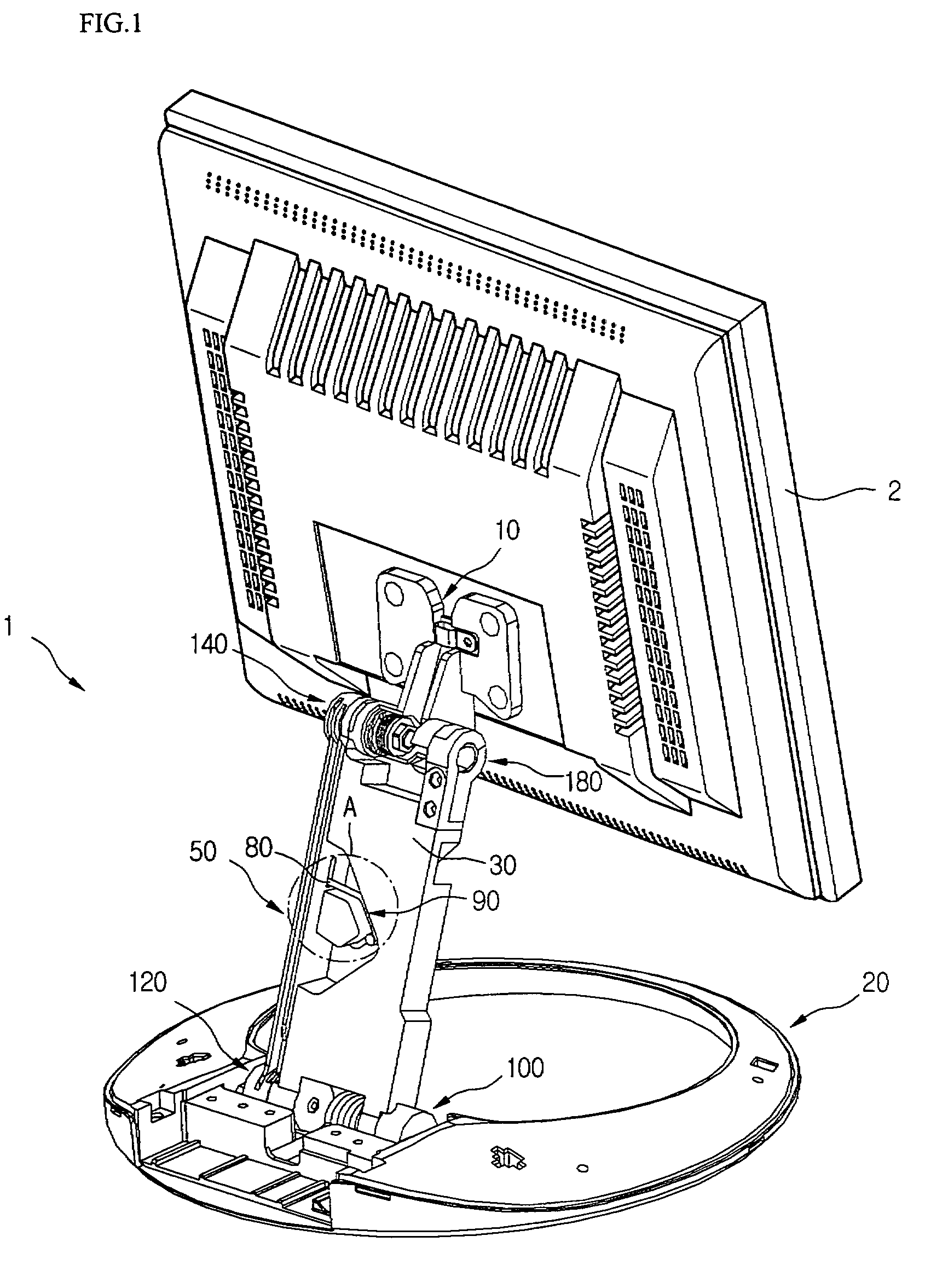
[0032]FIG. 1 is a rear perspective view of a stand 1 installed on a display device according to a first embodiment of the present invention.

[0033]Referring to FIG. 1, the stand 1 includes a supporting unit 10 fixed to a rear surface of a display device 2 such as a liquid crystal display (LCD) monitor for supporting the display device 2, a base unit 20 for placing the display device 2 on a floor, and a main link30 rotatably connected between the supporting unit 10 and the base unit 20.

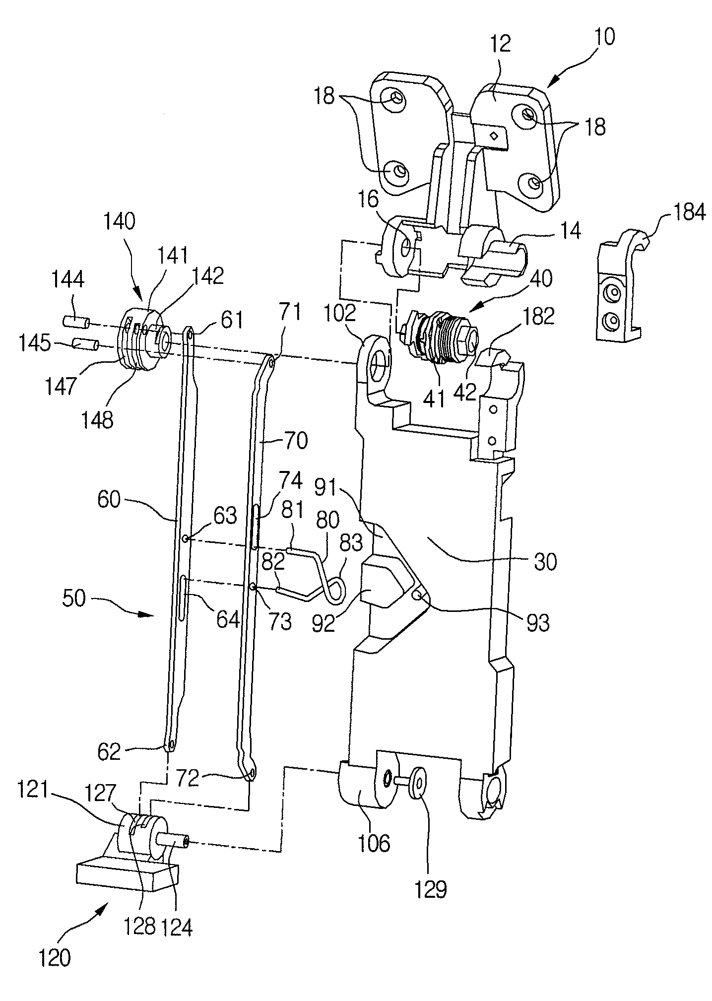
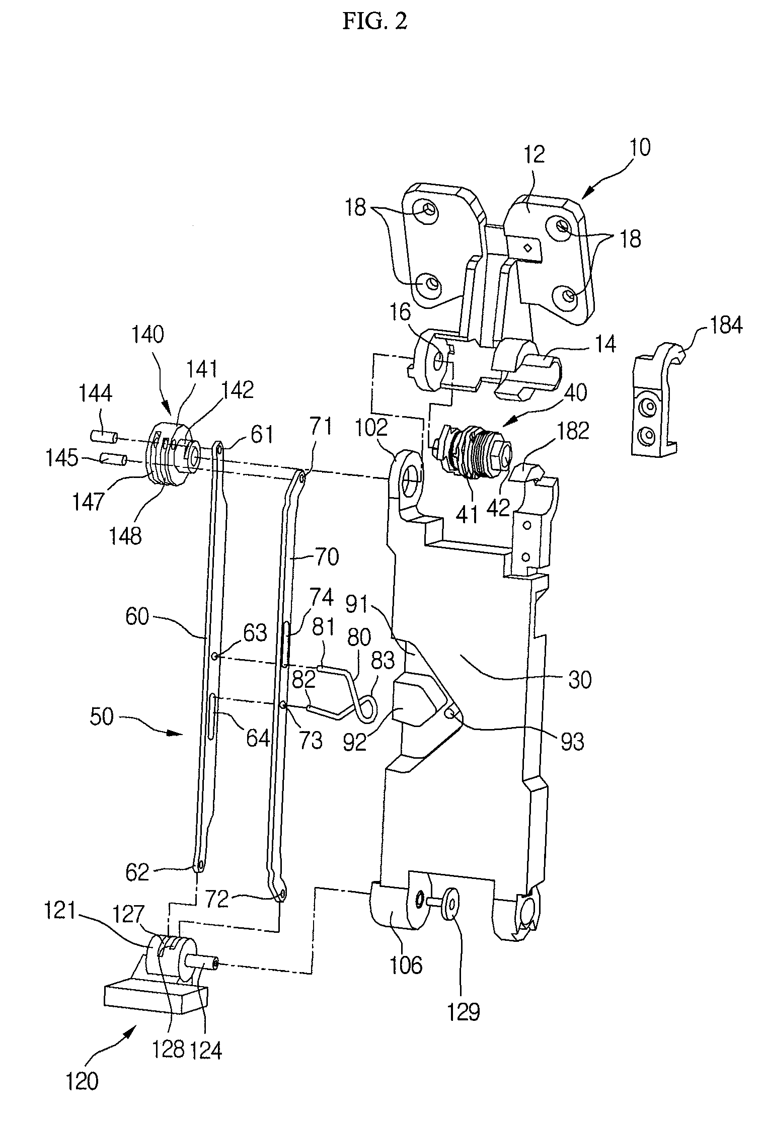
[0034]The stand 1 further includes a auxiliary link unit 50 connected between the supporting unit 10 and the base unit 20 beside the main link 30, and a torsion spring 80 installed on the auxiliary link unit 50. The torsion spring 80 includes a center portion accommodated in a torsion spring receiving portion 90 formed in one side of the main link unit 30.

[0035]In detail, the supporting unit 10 is rotatably connected to the main link unit 30 by a first link hinge 180 and a second link hinge 140. The mai...

second embodiment

[0089]In the second embodiment of the present invention, the stand has the same structure as in the first embodiment, except for the structure and shape of the torsion spring. Thus, descriptions of the same structure and elements will be omitted.

[0090]FIG. 7 is an enlarged view showing a torsion spring 200 of a stand and a neighboring structure of the torsion spring 200 according to the second embodiment of the present invention.

[0091]Referring to FIG. 7, the shape and structure of the torsion spring 200 are different from those of the torsion spring 80 of the first embodiment. In detail, the torsion spring 200 has ends 201 and 202 that are coupled to a auxiliary link unit in the same manner as in the first embodiment. However, the torsion spring 200 includes a wound portion 203 corresponding to a portion around the center hole 83 of the torsion spring 80 of the first embodiment. The wound portion 203 of the torsion spring 200 is formed by winding the center portion of the torsion s...

third embodiment

[0093]In the third embodiment of the present invention, the stand has the same structure as in the first embodiment, except for the structure and shape of the torsion spring and the torsion spring supporting structure. Thus, descriptions of the same structure and elements will be omitted.

[0094]FIG. 8 is an enlarged view showing a torsion spring 300 and a neighboring structure in a stand according to the third embodiment of the present invention.

[0095]Referring to FIG. 8, the structure of the torsion spring 300 is different from that of the torsion spring 80 of the first embodiment. In detail, the torsion spring 300 has one end 301 and a center hole 303 that are coupled to a auxiliary link unit in the same manner as in the first embodiment. However, the torsion spring 300 includes the other end 302 that is supported by a lower portion of a spring mount 92 but not connected or coupled to the auxiliary link unit. The other end 302 of the torsion spring 300 does not move when the one en...


PUM


Abstract

There is provided a stand for a display device. The stand includes a base unit supporting the display device. A main link unit is hinged between the display device and the base unit. A pair of auxiliary links is eccentrically connected to hinges of the main link unit at different positions. A torsion spring includes at least one end connected to the pair of auxiliary links for applying an elastic force to the pair of auxiliary links. The main link unit has a smaller thickness, and thus the size of the stand can be reduced. The stand allows for convenient and smooth operation of the display device. Further, since the spring has a simple structure, the stand can be manufactured through a simple process with less cost. Furthermore, the outer appearance of the stand can be simple.

Description

BACKGROUND OF THE INVENTION[0001]1. Field of the Invention[0002]The present invention relates to a stand for a display device, and more particularly, to a stand for a display device having an enhanced elastic member for the stand so as to be provided with a small main link and to be smoothly movable.[0003]2. Description of the Related Art[0004]A typical stand for a display device includes a base unit placed on a horizontal surface and a main link connecting the base unit to a monitor main body of the display device. The main link has a lower end rotatably supported by a pair of brackets fixed to the base unit, and an upper end connected to the monitor main body and allowing adjustment of the monitor main body to a desired tilting angle.[0005]A recent stand further includes a auxiliary link that facilitates unfolding of the main link. Generally, the auxiliary link includes two parallel link members and a tension spring (also referred to as a spring) disposed between the two link memb...

Claims


Application Information

Patent Timeline
Patent Type & Authority Patents(United States)
IPC IPC(8): A47G29/00F16M11/04
CPCF16M11/04F16M11/2021F16M11/10F16M2200/044Y10S248/917Y10S248/919Y10S248/922G06F1/1601
Inventor JANG, WOON GEUN
Owner LG ELECTRONICS INC
Why Eureka
Try Eureka