Swamp cooler filter

Inactive Publication Date: 2010-04-13
GENERA FELIPE +1
View PDF23 Cites 8 Cited by
  • Summary
  • Abstract
  • Description
  • Claims
  • Application Information

AI Technical Summary

Benefits of technology

[0013]One significant advantage of the present invention is to reduce the amount of time required to clean the piping of a swamp cooler and improve the efficiency of the swamp cooler.
[0014]It is an object of the present invention to provide a swamp cooler filter system which has all of the advantages of the prior art and none of the disadvantages.
[0015]It is another object of the present invention to provide a swamp cooler filter system which may be easily and efficiently manufactured and marketed.
[0016]It is another object of the

Problems solved by technology

However, none of the filters are positioned within the swamp cooler to clean the lines within the swam

Method used


Image

  • Swamp cooler filter
  • Swamp cooler filter
  • Swamp cooler filter

Examples


Embodiment Construction

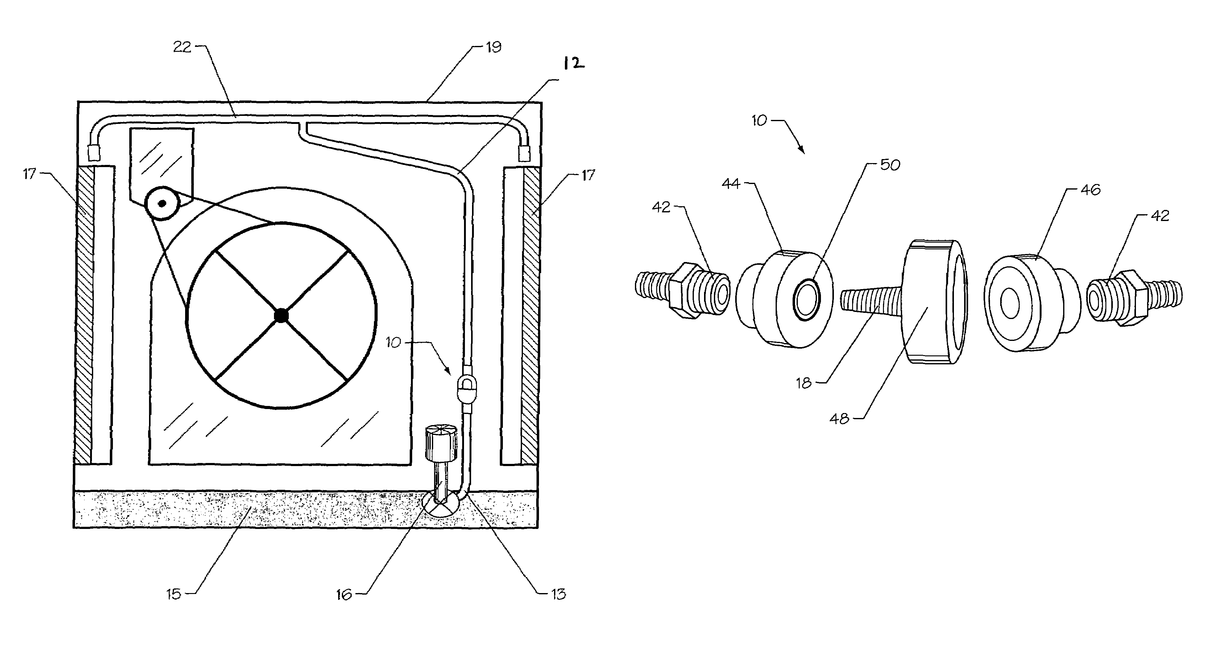
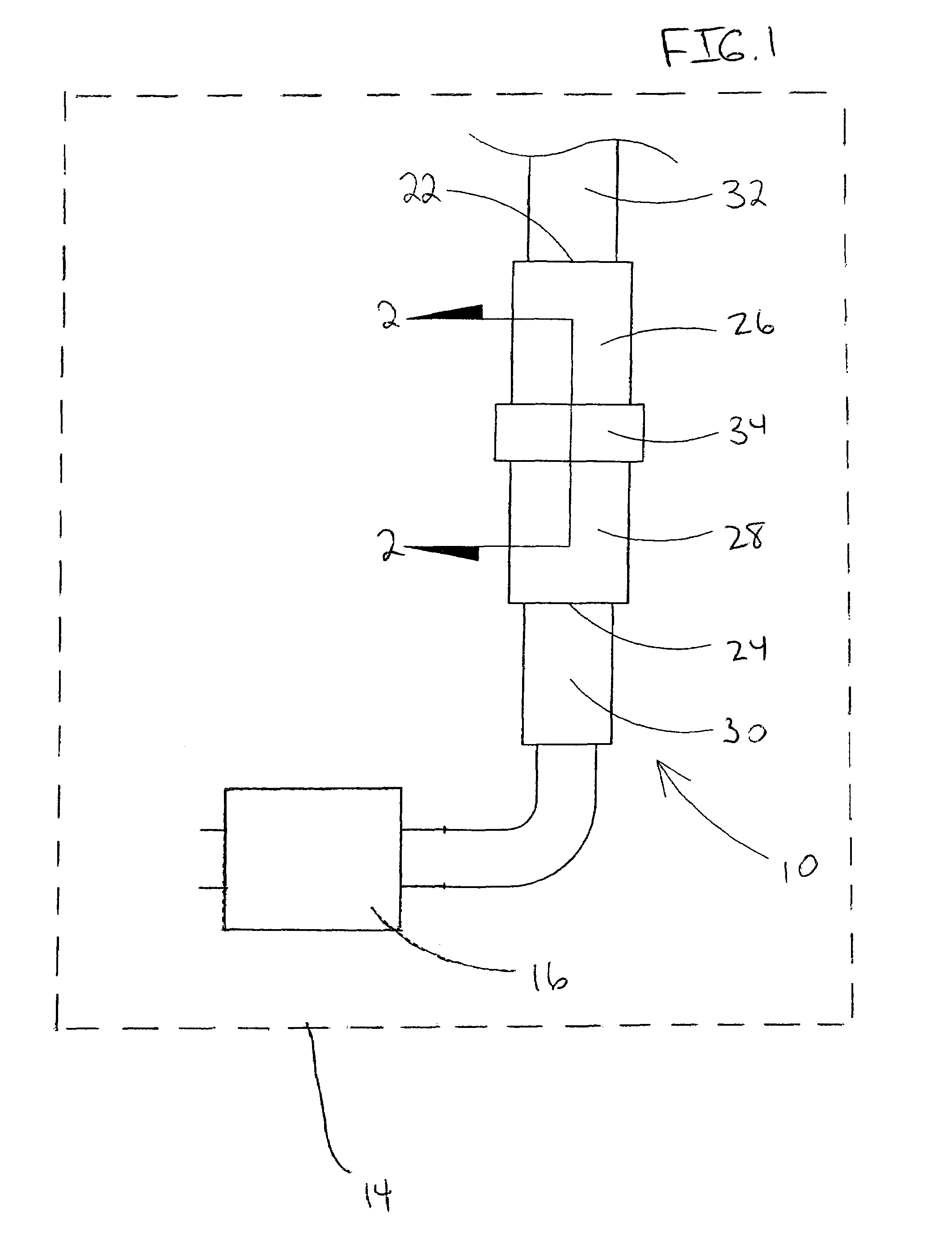
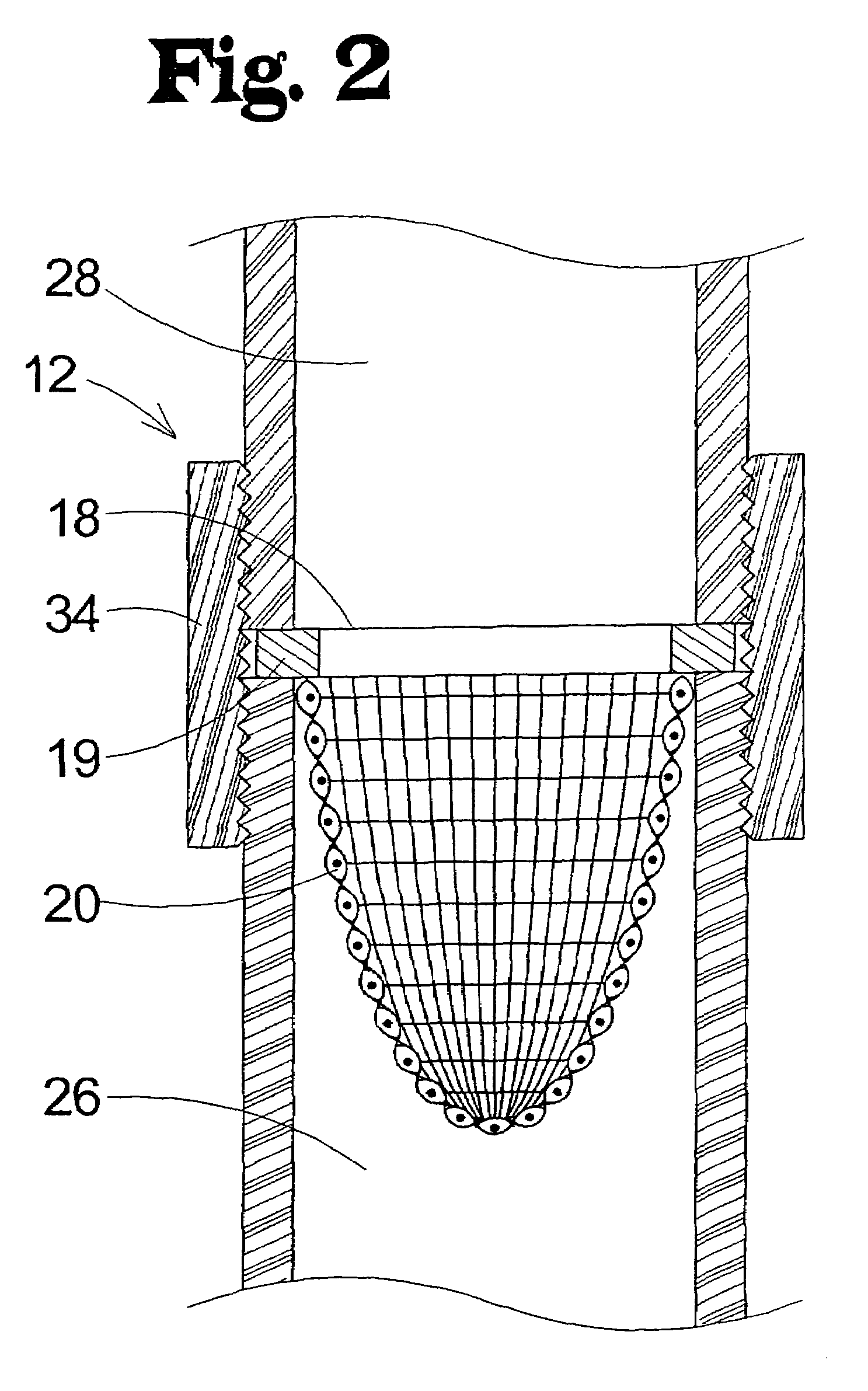
[0024]With reference now to the drawings, and in particular to FIGS. 1-4 thereof, a new swamp cooler filter embodying the principles and concepts of the present invention and generally designated by the reference numeral 10 will be described.

[0025]As best illustrated in FIGS. 1 and 4, the swamp cooler filter 10 of the present invention is positioned within a swamp cooler 14 and is not positioned outside the walls 19 of the swamp cooler 14. The swamp cooler 14 has a water pump 16 pumping water from a water reservoir 15 into a water intake hose 12. The water reservoir 15 is positioned at the base of the swamp cooler 14. The water pump 16 is positioned within the water reservoir 15 with the water intake hose 12 attached to the water pump 16. The swamp cooler filter 10 is positioned along the water intake hose 12 between the water pump 16 and the water intake lines 22. The water flows through the swamp cooler filter 10 into the water intake lines 22 and trickles onto the cooler pads 17....


PUM

PropertyMeasurementUnit
Diameteraaaaaaaaaa
Surface areaaaaaaaaaaa

Abstract

A swamp cooler filter for filtering debris from fluid drawn from a fluid reservoir for a swamp cooler is provided. The swamp cooler filter includes a water intake hose being operationally coupled to a swamp cooler whereby the water intake hose is in fluid communication between a fluid reservoir and a pump of the swamp cooler. A filter member is selectively positioned in the water intake hose. The filter member is for filtering debris from the fluid being drawn from the fluid reservoir by the pump to inhibit the debris being pumped through the swamp cooler by the pump.

Description

[0001]The present application is a continuation and claims benefit of priority of patent application Ser. No. 10 / 942,567, filed on Sep. 17, 2004, now abandoned entitled “Swamp Cooler Filter”.BACKGROUND OF THE INVENTION[0002]1. Field of the Invention[0003]The present invention relates to evaporative cooler pump assemblies and more particularly pertains to a new swamp cooler filter for filtering debris from fluid drawn from a fluid reservoir for a swamp cooler.[0004]2. Description of the Prior Art[0005]The use of evaporative cooler pump assemblies is known in the prior art. More specifically, evaporative cooler pump assemblies heretofore devised and utilized are known to consist basically of familiar, expected and obvious structural configurations, notwithstanding the myriad of designs encompassed by the crowded prior art which have been developed for the fulfillment of countless objectives and requirements.[0006]In the past, filters have been used for filtering debris from water line...

Claims


Application Information

Patent Timeline
IPC IPC(8): F28D5/02B01D29/11
CPCB01D35/02F28F19/01B01D2201/02
Inventor GENERA, FELIPEGENERA, EVA
Owner GENERA FELIPE
Why Eureka
Try Eureka