Automated excavation machine

a technology of automatic excavation and excavating machine, which is applied in the field of excavators, can solve the problems of increasing mining costs, mining personnel injuries, and deaths, and achieve the effect of efficient and effective excavating in situ materials

Inactive Publication Date: 2010-04-13
MIN OF NATURAL RESOURCES CANADA
View PDF197 Cites 95 Cited by
  • Summary
  • Abstract
  • Description
  • Claims
  • Application Information

AI Technical Summary

Benefits of technology

[0007]These and other needs are addressed by the various embodiments and configurations of the present invention. The present invention provides a remotely operable and/o

Problems solved by technology

Annually, underground mining of valuable materials is the cause of numerous injuries to and deaths of mine personnel.
The resulting measures required to comply with the regulations have been a contributing cause of significant increases in underground mining costs.
Further increases in mining costs are attributable to global increases in labor costs generally.
Increases in mining costs have caused numerous low grade deposits to be uneconomic to mine and therefore caused high rates of inflation in consumer products.
Although success has been realized in developing machines to mine materials continuously in soft deposits, such as coal, soda ash, talc, and other sedimentary material

Method used


Image

  • Automated excavation machine
  • Automated excavation machine
  • Automated excavation machine

Examples


Embodiment Construction

The Excavator

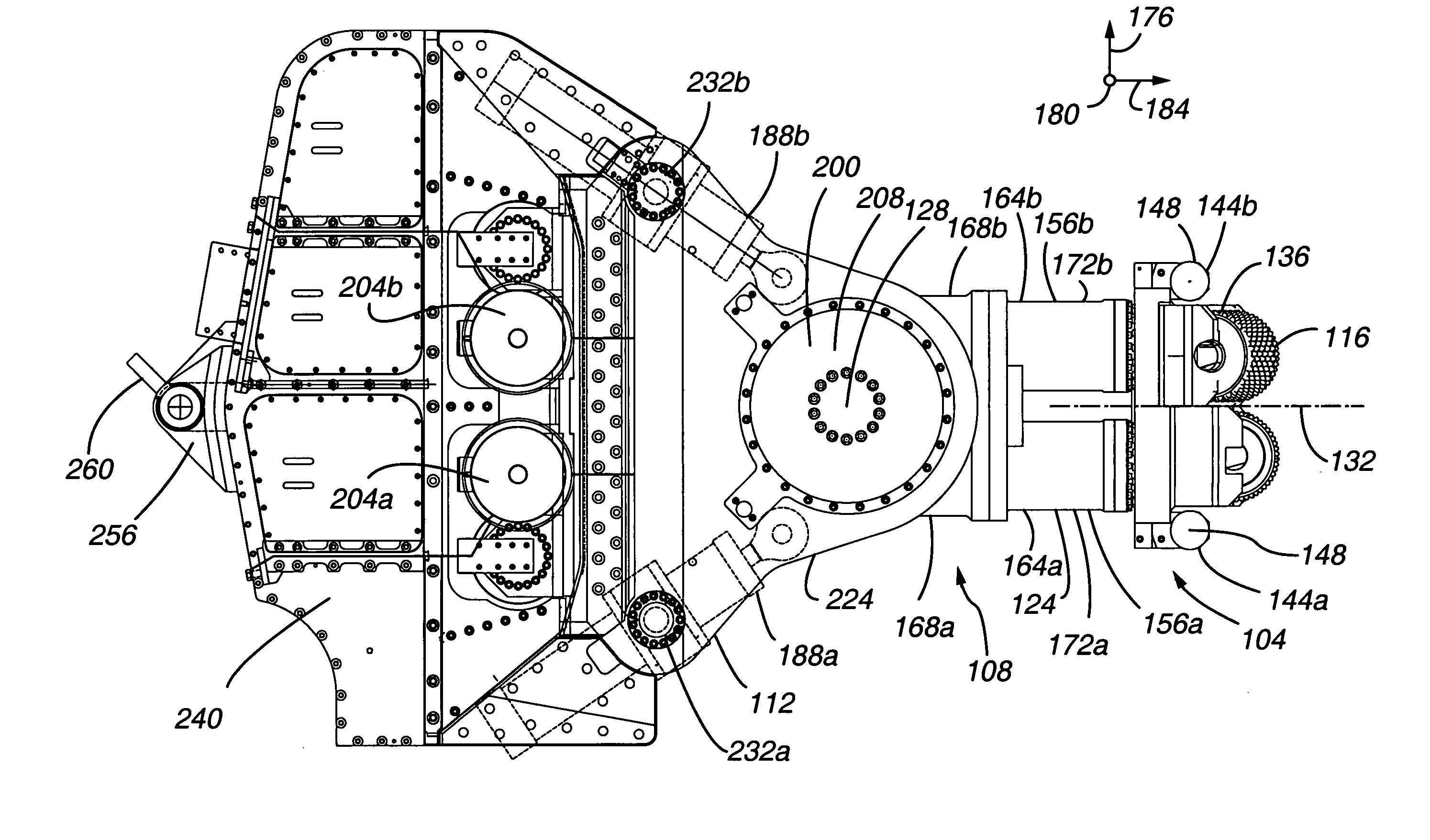
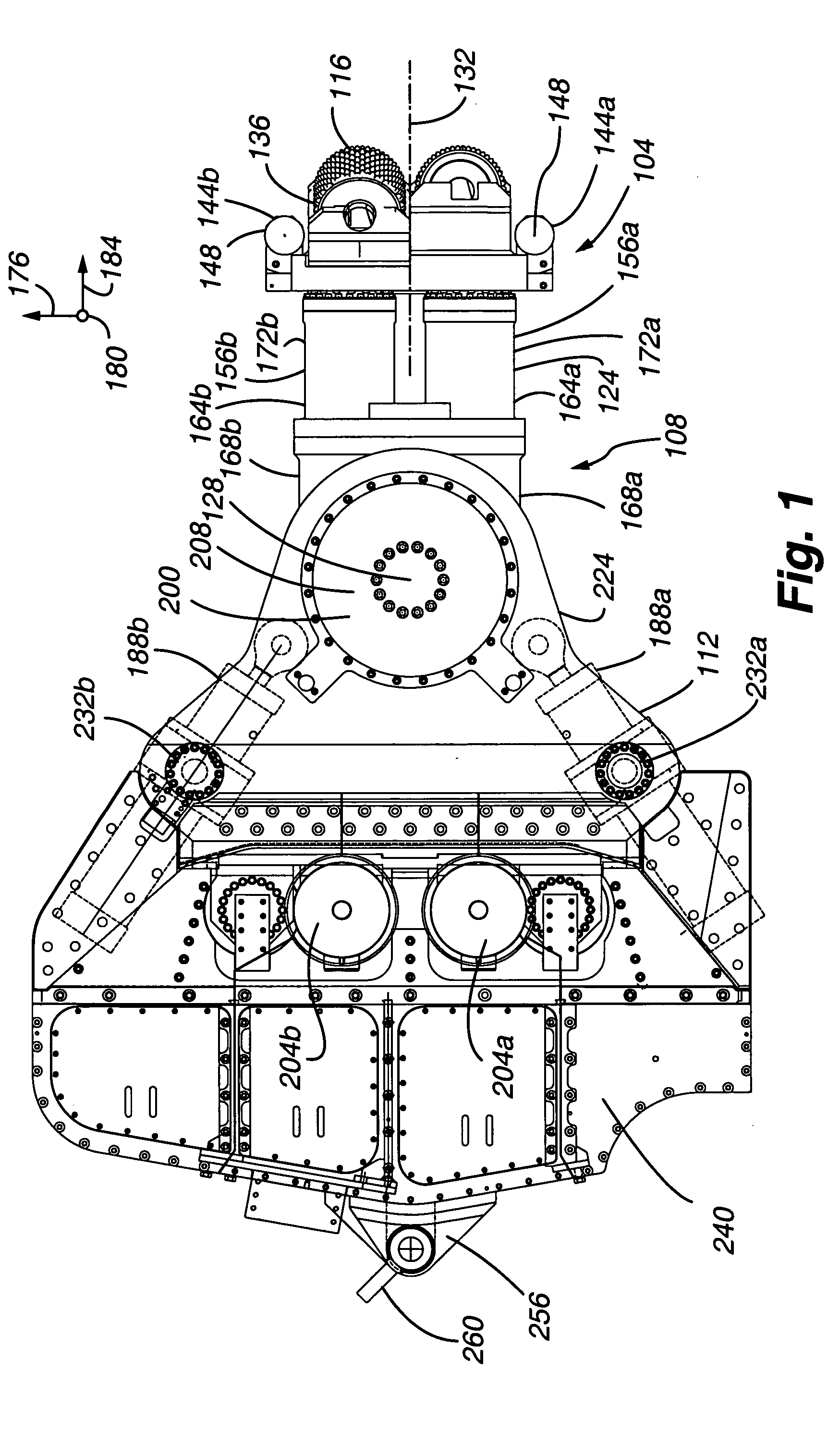
[0074]FIGS. 1-6 depict an excavator according to the present invention. The excavator 100 includes a cutter head 104 mounted on a swinging boom assembly 108 and an anchorable body 112.

[0075]The cutter head 104 mounts a plurality of overlapping cutting discs or rollers 116, such as rolling type kerf cutters, carbide cutters, button cutters, and disc cutters. The rear end 120 of the boom 124 is rotatable about a rotational axis 128 passing through the anchorable body 112 and normal to the plane of the page (FIG. 1) and to the length or longitudinal axis 132 of the boom 124.

[0076]The cutter head 104 typically excavates rock by breaking rock in compression during boom rotation or swings. The discs or rollers work by applying high point loads to the rock and crushing a channel through the rock. The pressure exerted by the discs or rollers in turn breaks small wedges of rock away from the edge of the discs or rollers, thereby excavating the rock. The array of discs or rollers...


PUM


Abstract

The present invention is directed to an excavator that is operable in manual and automatic modes and uses state machines to effect unit operations, rotationally offset swing actuators to rotate boom and cutter head, a fail safe hydraulic system to maintain gripper pressure in the event of a malfunction of the hydraulic system, differing position and pressure control functions in the hydraulic actuators, a kinematic module to effect pitch and roll adjustments, a cutting face profile generator to generate a profile of the excavation face, and an optimization module to realize a high degree of optimization of excavator operation.

Description

CROSS REFERENCE TO RELATED APPLICATIONS[0001]This application claims the benefits of U.S. Provisional Patent Application Ser. Nos. 60 / 440,995, filed Jan. 17, 2003; 60 / 431,188, filed Dec. 4, 2002; 60 / 418,716, filed Oct. 15, 2002; and 60 / 419,048, filed Oct. 15, 2002, each of which is incorporated herein by this reference.[0002]Cross reference is made to copending U.S. patent application Ser. No. 10 / 309,237, filed Dec. 4, 2002, which contains subject matter related to the subject matter of the present application.FIELD OF THE INVENTION[0003]The present invention relates generally to excavators and specifically to underground mining excavators.BACKGROUND OF THE INVENTION[0004]Annually, underground mining of valuable materials is the cause of numerous injuries to and deaths of mine personnel. Governments worldwide have enacted restrictive and wide-ranging regulations to protect the safety of mine personnel. The resulting measures required to comply with the regulations have been a contri...

Claims


Application Information

Patent Timeline
IPC IPC(8): E21C25/00E21C25/16E21C35/24E21C41/16
CPCE21C25/16E21C41/16E21C35/24
Inventor JACKSON, ERICHIRTZ, HALDALE, JAMESJORDAN, JOHNEDDY, DAVIDJACKSON, SIMON MARK
Owner MIN OF NATURAL RESOURCES CANADA
Why Eureka
Try Eureka