Deburring welded pipe

a technology of welded pipe and deburring device, which is applied in the direction of manufacturing tools, soldering devices, auxillary welding devices, etc., can solve the problems of inability to provide a robust method of adjusting cutters or depths, and the conventional deburring device is not adjustable for “in-process” and other problems, to achieve the effect of maximizing the use of cutting tool inserts, simple design and economical manufacture and assembly

Inactive Publication Date: 2010-04-13
LUMCO MFG
View PDF36 Cites 6 Cited by
  • Summary
  • Abstract
  • Description
  • Claims
  • Application Information

AI Technical Summary

Benefits of technology

[0007]At least some of the objects, features and advantages that may be achieved by at least certain embodiments of the invention include providing a welded pipe manufacturing method and related tooling that enables: adjustment of cutter rotation or a depth of cut on an in-process basis; adjustment of rotation of a cutter holder to maximize use of a cutting tool insert from one side of the insert to another; wherein the tooling is of relatively simple design, economical manufacture and assembly, rugged, durable, reliable, and in service has a long useful life.

Problems solved by technology

But conventional deburring devices typically are not adjustable for “in-process” cutter changes and / or depth of cut changes, during the pipe manufacturing operation and, at the very least, are not adjustable over a plurality of incremental or infinitely variable adjustment positions.
Moreover, the inside of the pipe is a very high temperature environment and conventional deburring devices do not provide a robust method of adjusting cutters or depth of cut on an in-process basis.

Method used


Image

  • Deburring welded pipe
  • Deburring welded pipe
  • Deburring welded pipe

Examples


Embodiment Construction

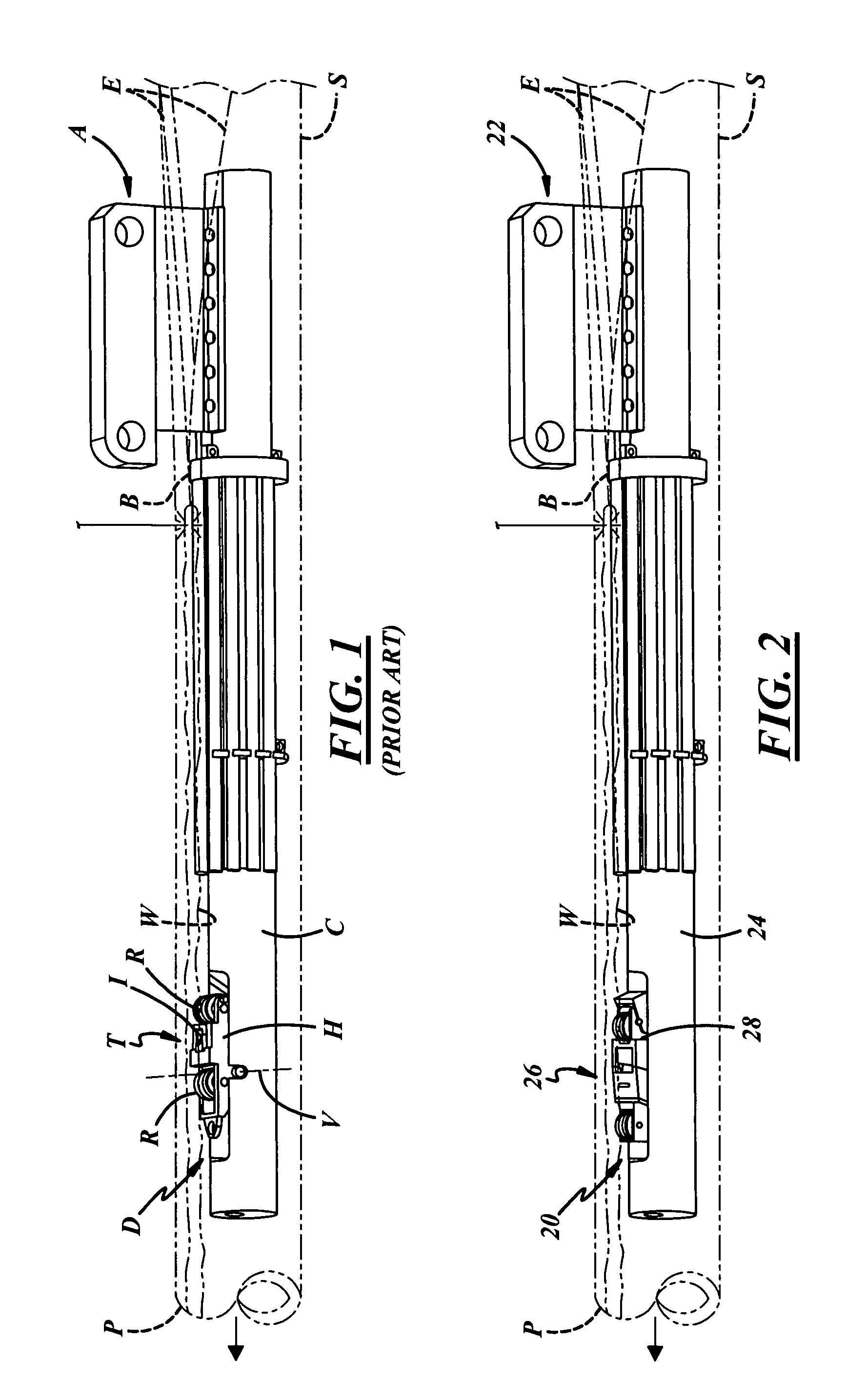
[0022]Referring in more detail to the drawings, FIG. 2 illustrates a pipe manufacturing arrangement in which a strip of metal or skelp S is unrolled from a coil of sheet metal (not shown), the skelp S is curled into a cylindrical shape by bringing laterally opposed edges E of the skelp S together to form a seam B, and the seam B is butt welded, thereby leaving a radially inwardly extending weld bead W. The weld bead W is removed with a deburring apparatus 20 as a freshly formed pipe P is fed downstream over the deburring apparatus 20.

[0023]The deburring apparatus 20 removes or deburrs the weld bead W from an internal surface of the welded pipe P. The deburring apparatus 20 may include a support arm 22 suspended from a welding machine (not shown), a cylinder 24 carried by the support arm 22 and projecting into an upstream end of the pipe P, and deburring tooling 26 carried at a downstream end of the cylinder 24.

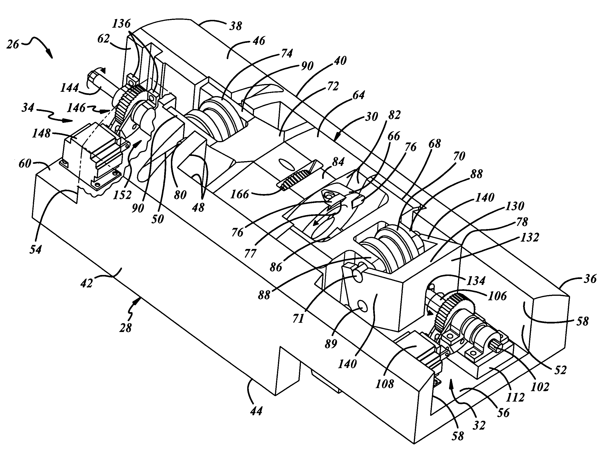
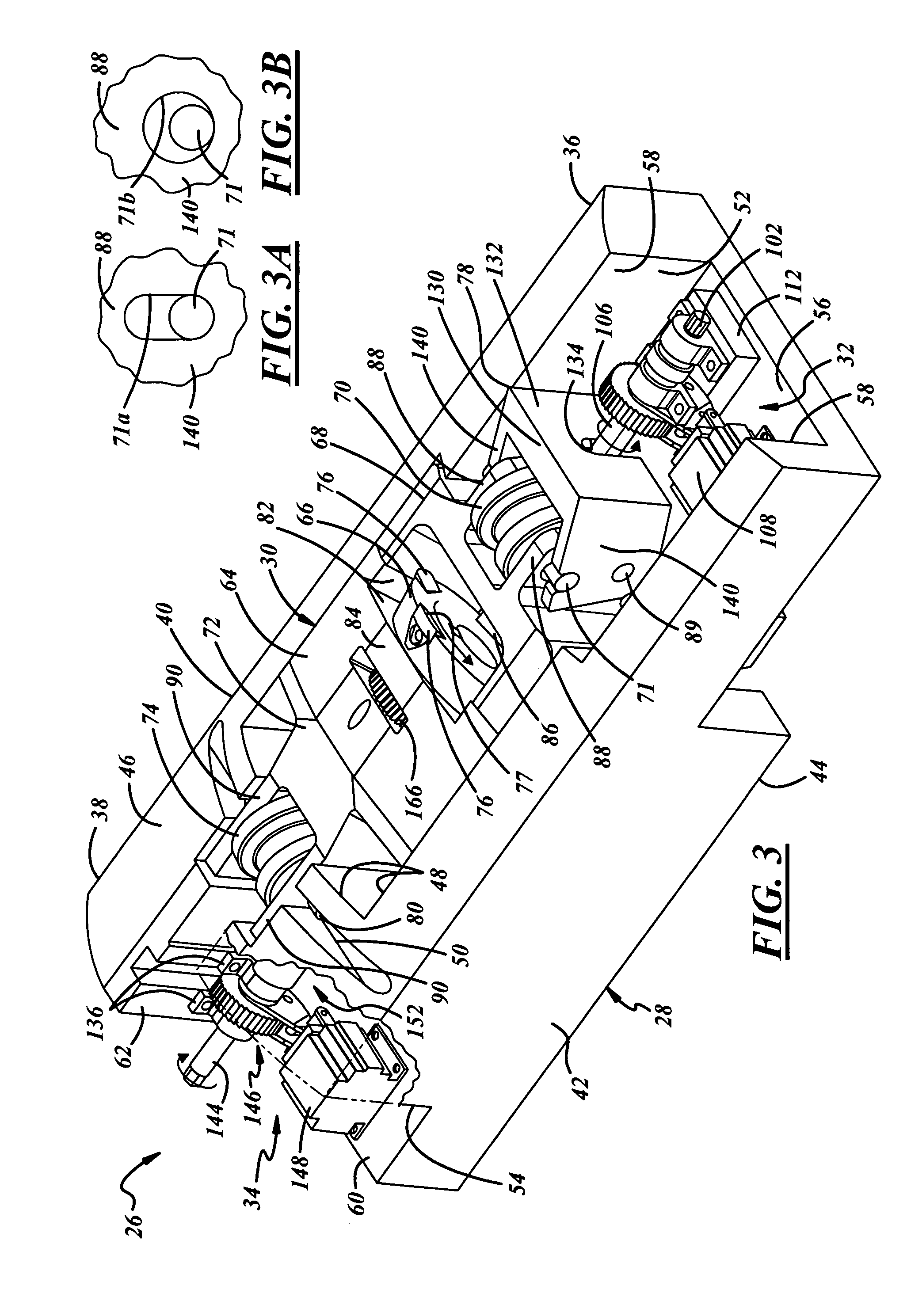
[0024]Referring to FIG. 3, the deburring tooling 26 generally includes a ...


PUM

PropertyMeasurementUnit
diameteraaaaaaaaaa
diameteraaaaaaaaaa
depthaaaaaaaaaa

Abstract

Methods of producing a pipe include curling a skelp into a cylindrical shape by bringing laterally opposed edges of the skelp together to form a seam, butt welding the seam to define the pipe downstream of the skelp, thereby leaving a radially inwardly extending weld bead. The weld bead is deburred off the pipe according to a depth of cut of a cutting tool. The depth of cut may be adjusted during deburring, and / or rotation of the cutting tool may be adjusted during deburring. The methods may be carried out using one or both of an adjustment device carried by a housing to pivot an adjustment member for adjustment of an upstream guide to adjust a depth of cut of the cutting tool into the weld bead, or an adjustment device carried by the housing and coupled to the cutting tool to rotate the cutting tool during deburring.

Description

FIELD OF THE INVENTION[0001]The present invention relates generally to material removal processes such as planing, and more particularly to deburring a weld bead from an internal surface of a pipe.BACKGROUND OF THE INVENTION[0002]Various types of pipe may be manufactured according to many different processes. For example, oil field pipe of three to four feet in diameter and 80 to 100 feet in length is frequently welded from sheet stock in a longitudinally continuous manner according to several simultaneous steps. For instance, as illustrated in prior art FIG. 1, a strip of metal or skelp S is unrolled from a coil of sheet metal (not shown). The skelp S is curled into a cylindrical shape by bringing laterally opposed edges E of the skelp S together to form a seam B. The seam B is butt welded, thereby leaving a radially inwardly extending weld bead W. The weld bead W is removed with a deburring apparatus D that remains stationary as a freshly formed pipe P is fed downstream over the d...

Claims


Application Information

Patent Timeline
Patent Type & Authority Patents(United States)
IPC IPC(8): B23D1/24
CPCB23D79/023B23K37/08Y10T409/501804Y10T409/509512Y10T409/501148
Inventor GLEASON, PATRICK J.
Owner LUMCO MFG
Why Eureka
Try Eureka