Electronic seal with radio frequency identification

a technology of electronic seals and radio frequency identification, applied in the direction of identification means, instruments, burglar alarms, etc., can solve problems such as failure of dfid system function, and achieve the effects of simplifying construction, pleasing product appearance, and suppressing emf noise interferen

Inactive Publication Date: 2010-04-13
ALEXAN
View PDF4 Cites 22 Cited by
  • Summary
  • Abstract
  • Description
  • Claims
  • Application Information

AI Technical Summary

Benefits of technology

[0025]So, the primary object of the present invention is to create an electronic seal with feature of far RF transmission range and unsusceptible to EMF noise interference as well as having beautiful product appearance. The other object of the present invention is to create an electronic seal with effect of endurable robust and solid construction as well as energy-saving and environmental protection.
[0026]In order to achieve the aforesaid objects, the lock cylinder and lock latching plug, which forms the integral lock portion of the present invention, comprises RF chip, RF antenna with associated electric circuits, conductors and RF chip to form a RFID system. If the lock cylinder and lock latching plug are separated, both of the built-in RF chip and RF antenna are then disconnected so that the DFID system becomes failed in function. Wherein, the signal transmission between RF chip and RF antenna is designed into coaxial feeding transmission manner with feature of shielding and suppressing EMF noise interference. The upper antenna tube and innermost waveguide pipe are coaxially sleeve construction with associated central relay conductor, which will electrically connect with (propagating conductor) to simplify the construction without loss of expected purpose.
[0027]Comparing with the conventional technology of the prior arts, innovative idea of simplifying construction is hidden in the coaxially sleeve construction of the (upper antenna tube) and innermost (waveguide pipe), which not only operates as an antenna pole but also serves as a part of lock cylinder as well as functions as switch of electrical connection with all mating components in the lock latching plug. Thus, the expected objects of decreasing usage of plastic material to have cost-saving, energy-conservation and environment-protective effects can be achieved.

Problems solved by technology

If the lock cylinder and lock latching plug are separated, both of the built-in RF chip and RF antenna are then disconnected so that the DFID system becomes failed in function.

Method used


Image

  • Electronic seal with radio frequency identification
  • Electronic seal with radio frequency identification
  • Electronic seal with radio frequency identification

Examples


Embodiment Construction

[0033]In order to facilitate your honorable examiners have better understanding the technological contents of the present invention, the detailed description for the preferred exemplary embodiment will be presented below with drawings associated.

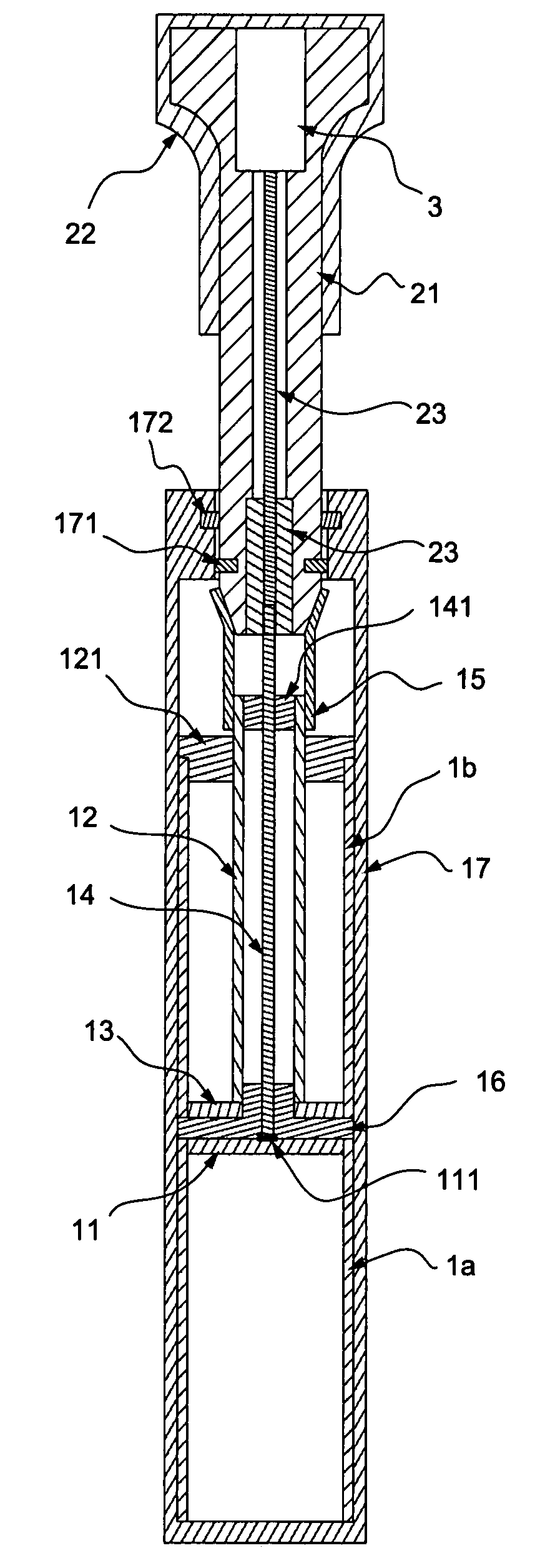
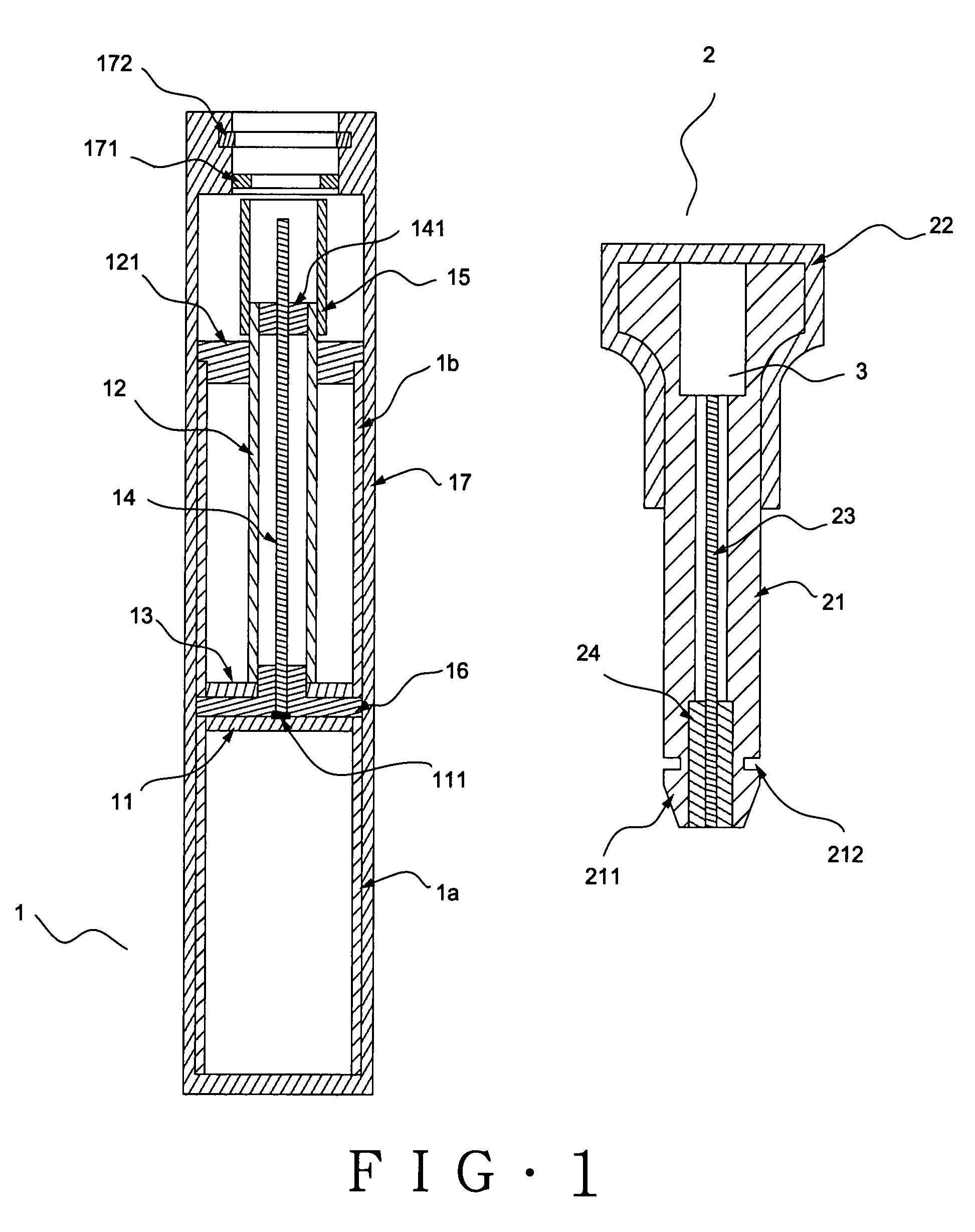
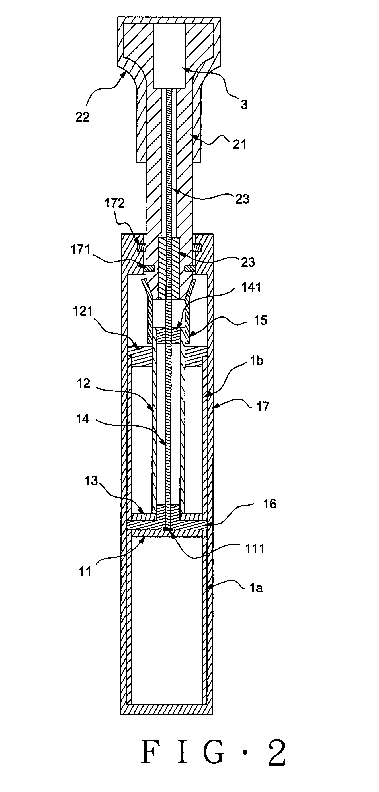
[0034]The FIG. 1 is the illustrative schematics showing the structure for a preferred exemplary embodiment of the present invention. Please refer to other drawings attached for cross reference. From these drawings clearly shown, the Electronic seal with radio frequency identification of the present invention mainly comprises a lock portion as well as a RF chip 3 and RF antenna 4 therein. The lock portion comprises a lock cylinder 1 and a lock latching plug 2 so that both of which can be interlocked as a lock in locking manner.

[0035]The lock cylinder 1 comprises a metal lower antenna tube 1a and a metal upper antenna tube 1b together with an insulation terrace gasket 16 and a barrel shell 17 surrounding outer, disposed on the lower end of sai...


PUM


Abstract

The electronic seal with radio frequency identification of the present invention comprises a lock cylinder and a lock latching plug to form an integral lock portion, which having RF chip, RF antenna with associated electric circuits, conductors and RF chip, wherein the lock cylinder comprises a metal lower antenna tube and a metal upper antenna tube to form each opposite pole of the dipole antenna. With relay conductor and propagating conductor being built in the central hollow space to connect with RF antenna and RF chip respectively, the RFID system is activated if lock cylinder and lock latching plug joint together.

Description

TECHNICAL FIELD[0001]The present invention relates to an electronic seal with radio frequency identification, particularly pertaining to the passive electronic seal used in container with dual function of conventional bullet-shaped electronic container lock and radio frequency identification (RFID) in an integral apparatus.PRIOR ARTS[0002]The purpose of the conventional container seal is to prevent the risk of enclosed commodity from being stealthily exchanged or stolen. But, due to the necessity of manual examination by the human eye inspect in such conventional container seal, the failure in expected function results in the manual negligence and mistake or forgery by other people is unavoidable. Currently, according to the official procedure in the manual transportation escort, the customs personnel should visit different customs territory to perform inspection that not only the administration cost is increased but also the time of customs clearance is delayed. Therefore, some bus...

Claims


Application Information

Patent Timeline
Patent Type & Authority Patents(United States)
IPC IPC(8): G08B13/14
CPCG09F3/0317G09F3/0376G09F3/0335
Inventor LAI, SIMON
Owner ALEXAN
Why Eureka
Try Eureka