
Multi-band jammer

a multi-band, jammer technology, applied in communication jamming, instruments, electrical equipment, etc., can solve the problems of single carrier jammer ineffectiveness, inability to effectively use single carrier jammers, and complex signal protocols that may be present in any particular local area

Inactive Publication Date: 2010-04-13
AEROFLEX WICHITA
View PDF4 Cites 27 Cited by
  • Summary
  • Abstract
  • Description
  • Claims
  • Application Information

AI Technical Summary

Problems solved by technology

In light of the increasing large deployment of many different types of RF transmitters and receivers, the particular RF signals and signal protocols that may be present in any particular local area potentially are quite complex.
However, the large deployment of many different types of RF transmitters and receivers has rendered conventional jammers ineffective in many RF environments.
However, such single carrier jammers have become ineffective and easily avoided using, for example, frequency hopping, spread spectrum and other technologies.
By way of example, a 200 MHz barrage jammer transmitting 100 Watts generally will only have 12 mWatts in any communications channel and this low power level per channel is likely to be ineffective as a jammer.
These jammers also tend to jam wanted communications.
The disadvantages of a DDS are that a) the jammer system must know which channels to jam requiring an involved signal processing system and b) the jammer system requires a large number of DDS's to cover all the possible active mobile station receive channels.
A disadvantage of the noise jammer system is that the noise density is low.
This low power produces a limited effective jammer range.
This mobile station circuitry is inexpensive, but the number of mobile stations that can be jammed at one time is limited.
Further, the mobile station circuitry has limited transmit power and therefore has a limited effective range.
Known systems do not satisfy these requirements.

Method used


Image

  • Multi-band jammer
  • Multi-band jammer
  • Multi-band jammer

Examples


Embodiment Construction

[0052]In digital systems, such as GSM systems, the signals are digital in nature having a number of bits per burst. Communications are jammed by jamming a small number of bits in each burst. The jamming of a small number of bits confuses the mobile station and / or the base station so that in either case the communications are prevented or stopped.

[0053]If the jamming burst is too short, the communication system may use Error Correction Coding (ECC) or otherwise overcome the disturbance to compensate for the short burst of bad bits such that the jamming is ineffective. If the jammer burst is too long, the system is wasting RF power that, particularly for battery operated portable jamming system, is in short supply.

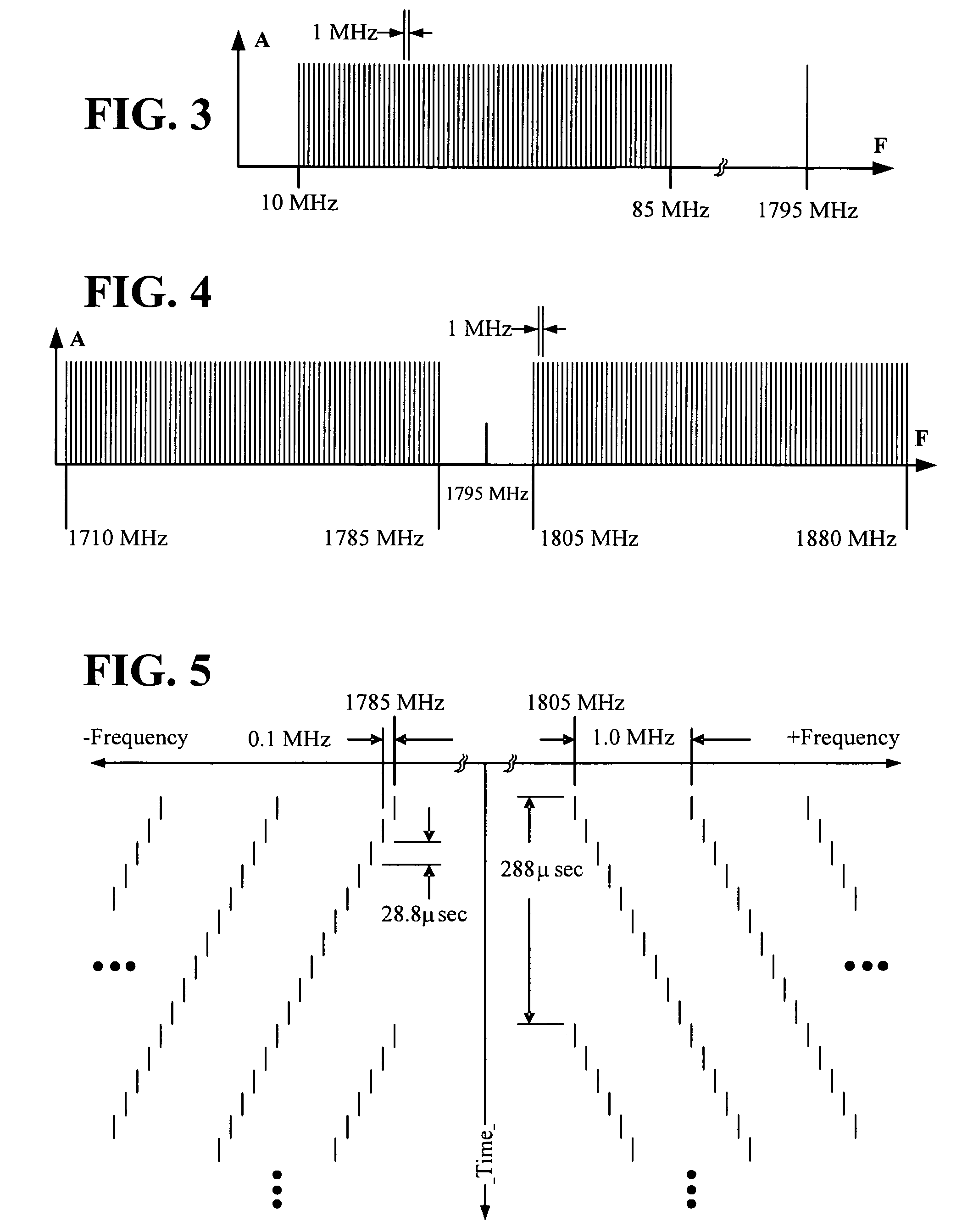
[0054]It has been found experimentally that if the jammer jams 20% of every TDMA burst in a GSM system for any particular mobile station, the communications for that mobile station are prevented or stopped. In order to jam 20% of every TDMA burst where each burst has a burst...


PUM


Abstract

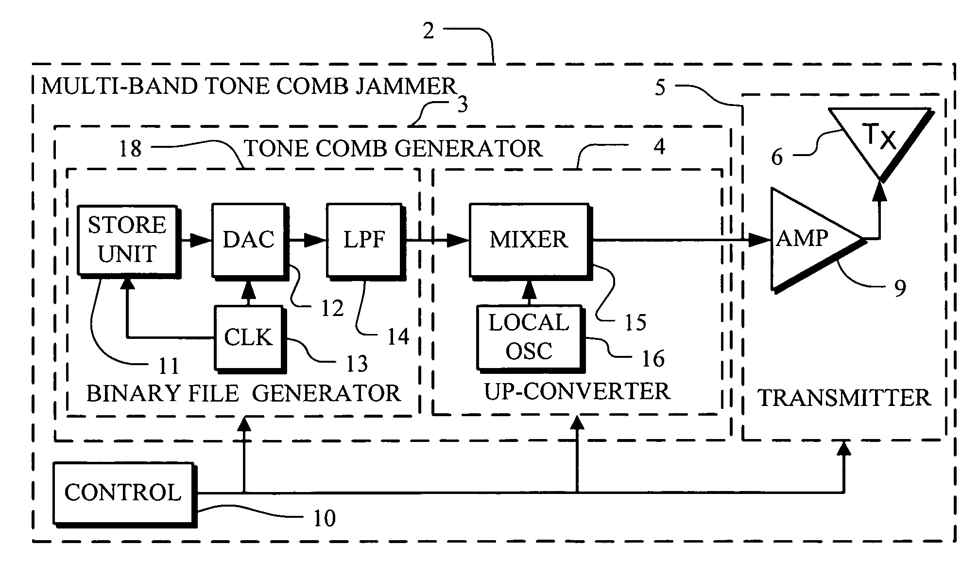
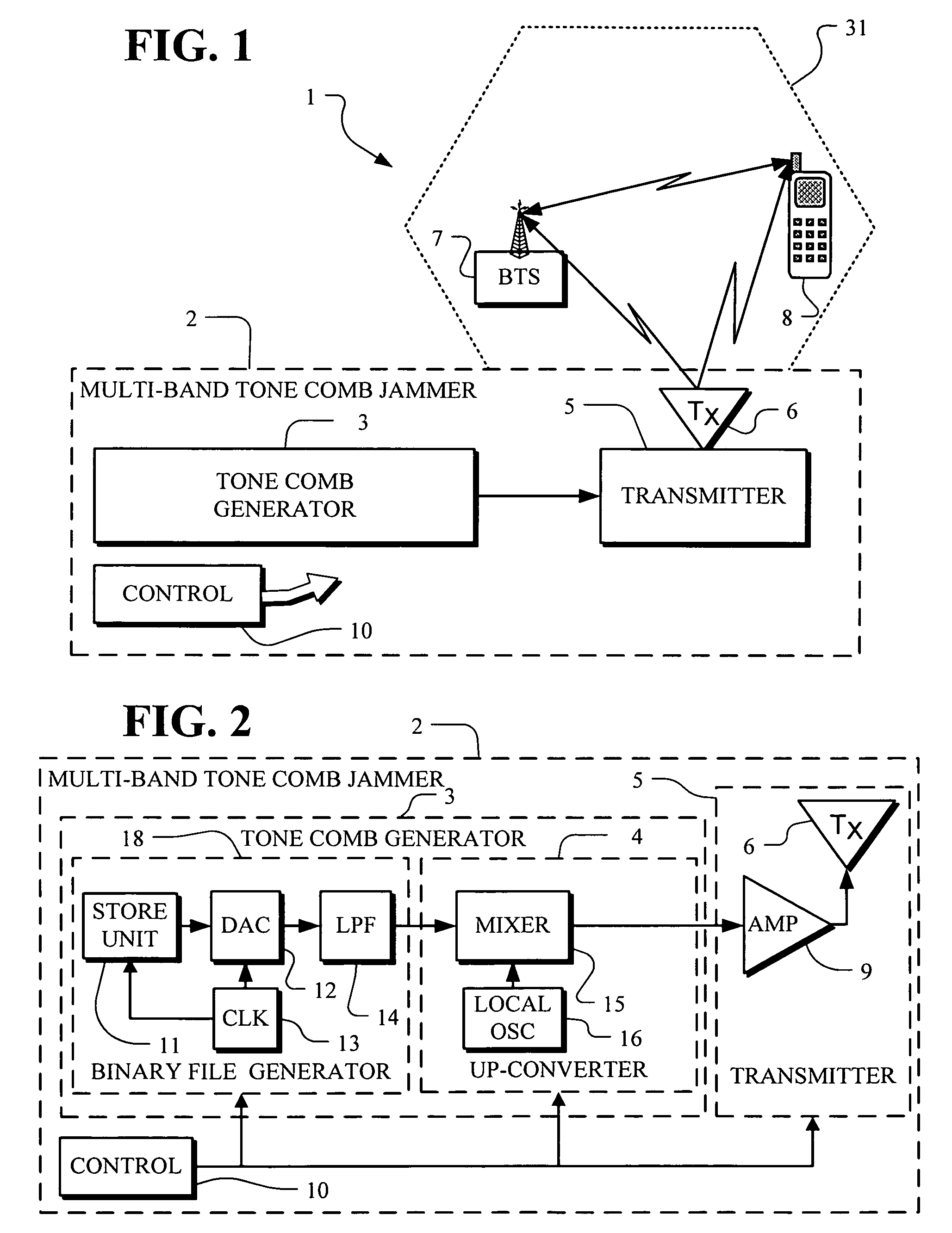
A jammer for jamming communications in a communications system where the communications system operates with digital bursts having burst periods measured in time and occurring in a communication frequency band such as GSM having a transmit band and a receive band. The jammer includes a tone comb generator for providing repetitions of jamming signals for the communication frequency band where the jamming signals have jamming signal intervals providing frequency separation between the jamming signals. The jamming signals are generated with a dwell time substantially less than a burst period for the communications system. The jamming signals are generated concurrently for the transmit band and the receive band and are transmitted as RF jamming signals to jam communications for mobile stations.

Description

TECHNICAL FIELD[0001]The present invention relates to RF transmitters and receivers in environments where inhibiting of RF communications is desired and further relates to RF jammers that jam communications with local mobile stations thus preventing such local mobile stations from communicating or otherwise from initiating any action.BACKGROUND OF THE INVENTION[0002]RF transmitters and receivers have become widely available and deployed for use in many applications including many commercial products for individuals such as cellular hand sets (“mobile stations”), garage door openers, automobile keyless entry devices, cordless handsets and family radios. RF transmitters and receivers are also widely deployed in more complex commercial, safety and military applications. Collectively, the possible existence of many different RF transmissions from many different types of equipment presents a broadband RF transmission environment.[0003]In light of the increasing large deployment of many d...

Claims


Application Information

Patent Timeline
Patent Type & Authority Patents(United States)
IPC IPC(8): H04K3/00H04B1/10H04B1/38
CPCH04K3/28H04K3/42H04K3/44H04K3/46H04K2203/16H04K2203/34H04K3/45
Inventor STODDARD, ROBERT EUGENE
Owner AEROFLEX WICHITA
Learn More