Method for operating a drive unit

a technology of drive unit and drive shaft, which is applied in the direction of position/direction control, stopper details, special data processing applications, etc., can solve the problems of increasing the inability to achieve the minimum possible output torque, so as to reduce the wear of the brake shaft

Inactive Publication Date: 2010-04-13
ROBERT BOSCH GMBH
View PDF24 Cites 9 Cited by
  • Summary
  • Abstract
  • Description
  • Claims
  • Application Information

AI Technical Summary

Benefits of technology

[0005]An object of the present invention is to refine a method in such a way that fuel consumption and, when used in a motor vehicle, brake wear are reduced. This object is achieved in a method by having the setpoint power output quantity, at least indirectly, be a function of the instantaneous transmission ratio of the transmission at least for a given intended power output. The above object is achieved accordingly in a computer program, an electric memory medium for a control and / or regulating device of an internal combustion engine, a control and / or regulating device for an internal combustion engine, and an internal combustion engine, in particular for a motor vehicle.
[0006]In the method according to the present invention, for a given intended power output, which in practice is usually a very low intended power output, the setpoint power output quantity is allowed to change on the basis of a change in the instantaneous transmission ratio. Although in these operating situations of the drive unit this may affect comfort, it is ensured that a minimum possible setpoint power output quantity is possible if this is desired by the user of the drive unit. When the engine is operated, energy is thus saved, and, when the drive unit is used in a motor vehicle, brake wear is also reduced.
[0007]It is first proposed that the dependence on the transmission ratio decrease continuously with increasing intended power output. Relatively great abrupt changes in the operating characteristics of the drive unit are thus prevented. In a motor vehicle in particular, operation is thus made easier.

Problems solved by technology

However, consistent implementation of this method in certain situations may result in more power being generated than necessary for operating the vehicle when the driver intends to stop the vehicle.
This minimum possible output torque—a braking torque in most operating situations of a motor vehicle—may therefore not be achieved if an abrupt torque jump is to be completely suppressed in shifting gears.
To nevertheless brake the vehicle as desired, the driver would have to actuate the brake, which in turn increases its wear.

Method used


Image

  • Method for operating a drive unit
  • Method for operating a drive unit
  • Method for operating a drive unit

Examples


Embodiment Construction

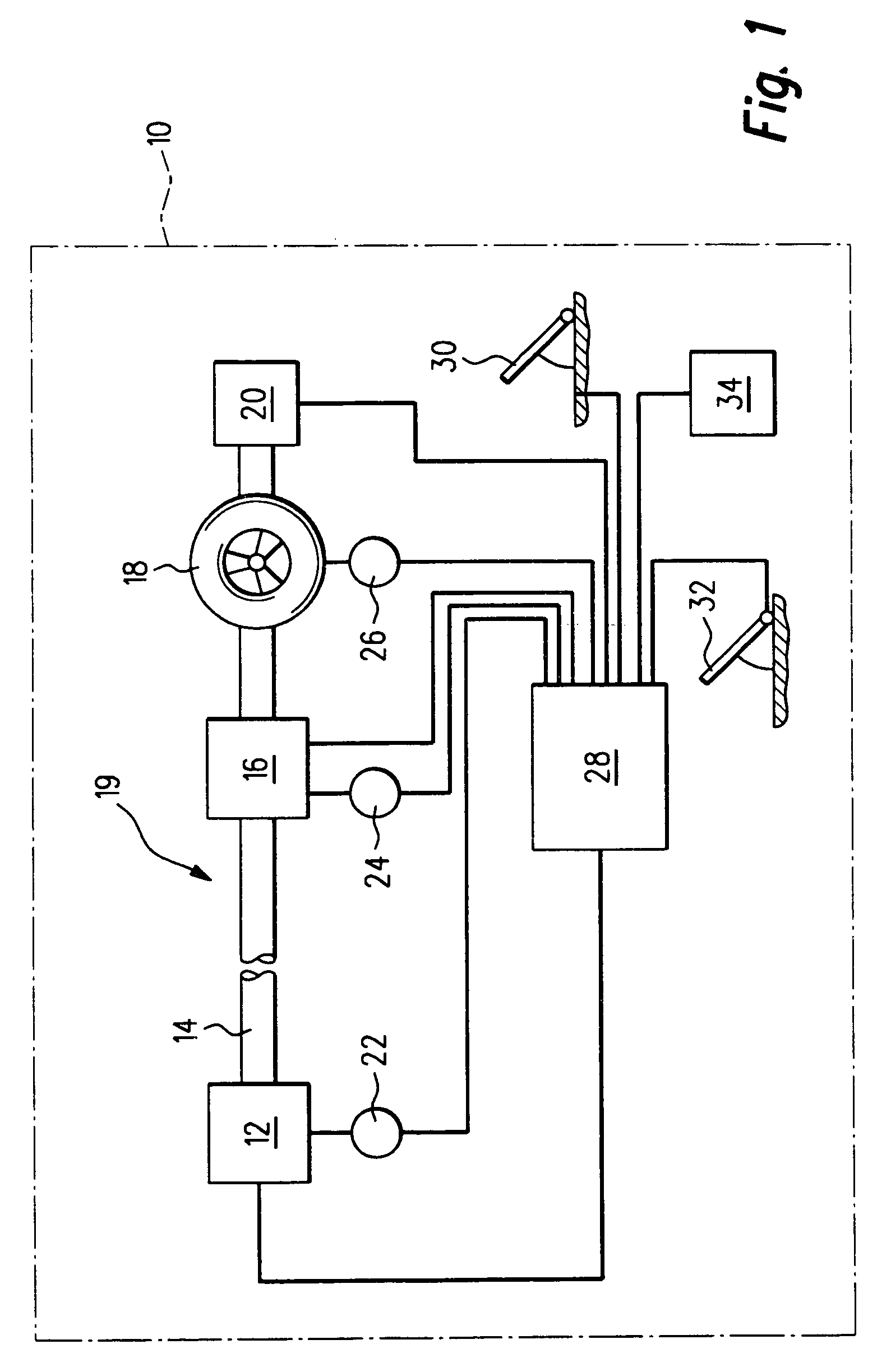
[0028]A motor vehicle is identified overall in FIG. 1 with the reference symbol 10. It includes an engine designed as an internal combustion engine 12, which sets a crankshaft 14 in rotary motion. It is connected to a transmission 16, which drives wheels 18 of motor vehicle 10, only one of which is illustrated. Engine and transmission are parts of a drive unit 19. A brake 20 also acts upon wheels 18.

[0029]Various instantaneous operating parameters of engine 12 are picked up by a sensor 22 illustrated as an example. These include, for example, an instantaneous operating temperature of the engine. Transmission 16 is an automatic multistage transmission, i.e., the transmission ratios of one gear differ from those of another gear (this is included here, as is a continuously variable transmission, not shown, under the term “variable transmission ratio”). The instantaneous gear is detected by a transmission sensor 24. The driving velocity is picked up at wheel 18 via velocity sensor 26.

[0...


PUM


Abstract

A drive unit includes an engine and a transmission having a variable transmission ratio. An instantaneous setpoint power output quantity of the drive unit is determined from an intended power output. The setpoint power output quantity is a function of the instantaneous transmission ratio of the transmission at least for a given intended power output.

Description

FIELD OF THE INVENTION[0001]The present invention first relates to a method for operating a drive unit which includes an engine and a transmission having a variable transmission ratio, in which an instantaneous setpoint power output quantity of the drive unit is determined from an intended power output. The present invention also relates to a computer program, an electric memory medium, a control and / or regulating device for an internal combustion engine, and an internal combustion engine.BACKGROUND INFORMATION[0002]A drive unit having an engine and a transmission having a variable transmission ratio is present, for example, in today's typical motor vehicles. Transmissions having a plurality of driving positions, i.e., gears, are used as transmissions. The intended power output may be expressed, for example, by the angular position of a gas pedal and normally corresponds to an intended torque. The setpoint power output quantity may be the setpoint output torque of the drive unit whi...

Claims


Application Information

Patent Timeline
Patent Type & Authority Patents(United States)
IPC IPC(8): G06F7/00G06F17/00
CPCF02D41/023F02D41/0225Y10T74/19251F02D41/12F02D2200/1006F02D2250/21Y10T477/89Y10T477/865Y10T74/19274Y10T74/1254Y10T477/75Y10T477/6333Y10T477/38Y10T477/675Y10T477/688Y10T477/347Y10T477/639B60W30/188B60W10/06
Inventor STREIB, MARTIN
Owner ROBERT BOSCH GMBH
Why Eureka
Try Eureka