Pyrotechnic actuator

a technology of actuators and actuators, applied in the field of actuators, can solve the problems of disadvantageous fast and uncontrolled movement of actuator elements, and achieve the effect of simple actuator design

Inactive Publication Date: 2010-04-20
AUTOLIV DEV AB
View PDF13 Cites 8 Cited by
  • Summary
  • Abstract
  • Description
  • Claims
  • Application Information

AI Technical Summary

Benefits of technology

[0011]In accordance with a preferred embodiment, the control means is arranged between the pressure element and the actuator element. It is thereby achieved that the gas pressure generated by the pyrotechnic pressure element does not build up abruptly, but increasingly in front of a surface of the actuator element which is to be acted on. This contributes to a yet more controlled movement of the actuator element.
[0013]The diaphragm is preferably integrated into a spacer means for the pressure element. The spacer means serves for the correct positioning of the pressure element in the actuator housing. The spacer means satisfies a dual function by the simultaneous integration of the diaphragm, whereby the number of the components is reduced and the design of the actuator is simplified.
[0014]In accordance with a further embodiment, grouting is provided for the pressure element. In the event of an activation of the pressure element, the grouting brings about a more uniform conversion of the chemical substances contained in the pressure element and thus results in a more uniform gas pressure. Ultimately, a more uniform action on the actuator element and consequently an even more controlled movement of the actuator element is thereby achieved.
[0015]In accordance with an advantageous embodiment, the actuator element is fixed in a starting position by a grouting element. The grouting element satisfies a dual function in that it forms grouting for the pressure element, on the one hand, and provides a fixing of the actuator element, on the other hand. The design of the actuator is thereby simplified even further.
[0018]In accordance with a further advantageous embodiment, a holding device is provided to hold the actuator element in an end position after a movement by the pressure element. The holding device has the effect that the actuator element cannot be simply returned back into its starting position from its end position after a triggering of the actuator. In other words, the movement of the actuator element is irreversible.
[0019]The holding device can include a knurling of the actuator element which is pressed into a bore of the actuator housing on a movement of the actuator element. Alternatively or additionally, the holding device can include a friction-retaining slope of the actuator housing in which the actuator element jams on its movement. Both variants represent a particularly simple form of a holding device for the actuator element and thus contribute to a simple design of the actuator.

Problems solved by technology

This fast and uncontrolled movement of the actuator element has proved to be disadvantageous in those applications in which the movement procedure of the actuator element should endure for a specific time and / or a bounce of the actuator element should be avoided, e.g. in locking or unlocking processes.

Method used


Image

  • Pyrotechnic actuator
  • Pyrotechnic actuator
  • Pyrotechnic actuator

Examples


first embodiment

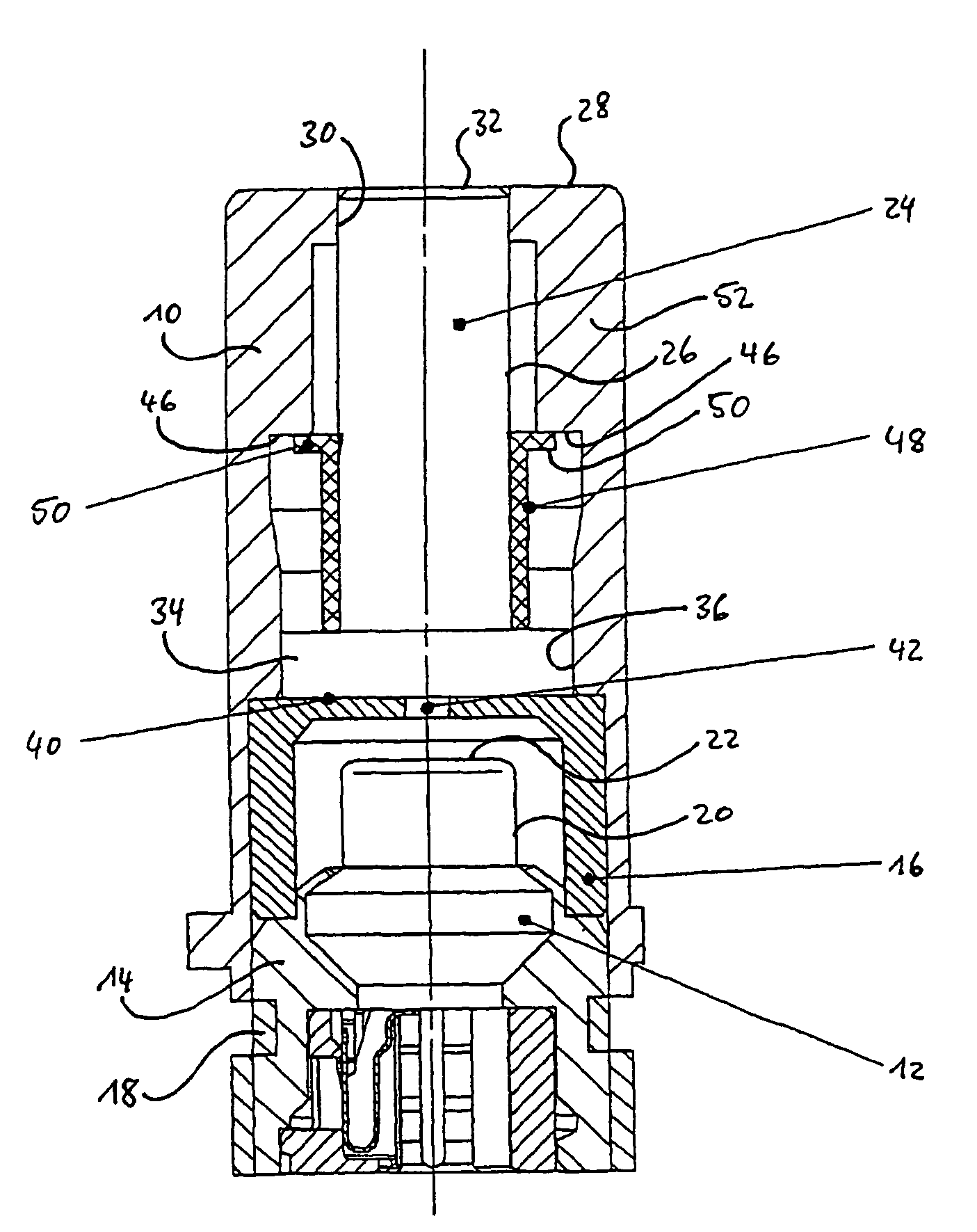
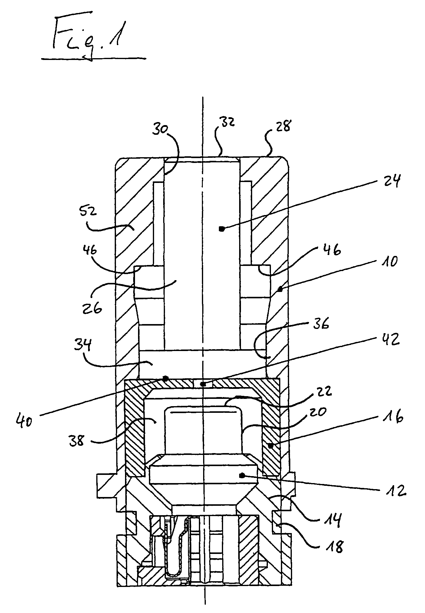
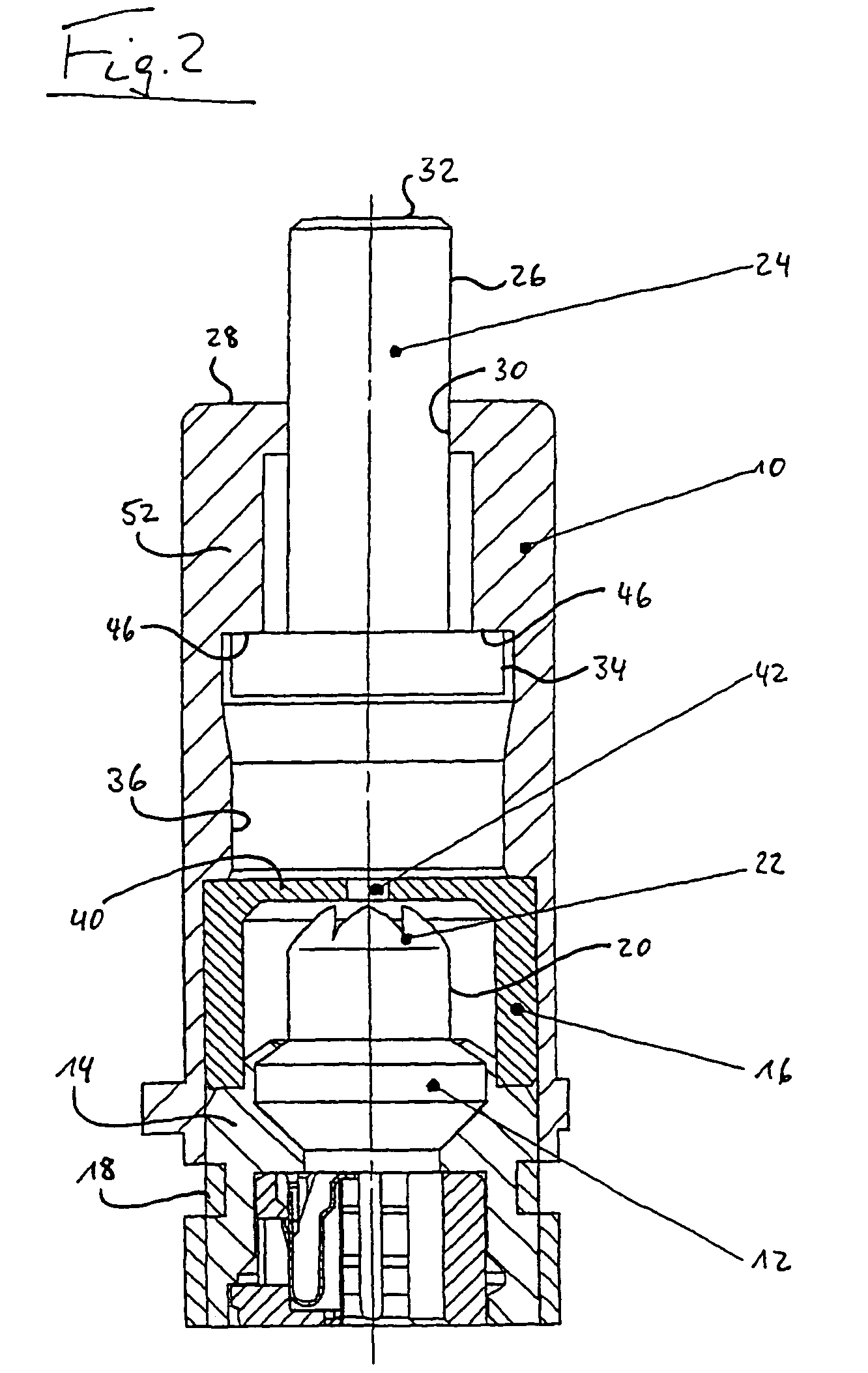
[0030]the pyrotechnic actuator in accordance with the invention is shown in FIGS. 1 and 2.

[0031]The actuator has an actuator housing 10 in which a pyrotechnic pressure element 12 is arranged. The pressure element 12 is held by a pressure element carrier 14 in a rear region, a lower region in the Figure, of the actuator housing 10.

[0032]For the correct positioning of the pressure element carrier 14 in the actuator housing 10, a beaker-shaped spacer cup 16 is provided whose open side faces the pressure element carrier 14 and which surrounds the pressure element 12 at least regionally. The pressure element carrier 14 is fixed to the actuator housing 10 by means of a clinching connection 18.

[0033]Ignitable chemical substances are contained in the pyrotechnic pressure element 12 and can be brought to reaction, for example by electrical energy, on a triggering of the pressure element 12. Pressure elements of this type and suitable ignition mechanisms are sufficiently known.

[0034]A gas pre...

third embodiment

[0049]The knurling 54 pressed into the bore 30 in a slight interference fit and prevents the piston 24 fully pushed out of the actuator housing 10 from being able to be pushed back into the actuator housing 10. The actuator in accordance with the third embodiment therefore represents an irreversible system in which the piston 24 can admittedly be moved out of the actuator housing 10, but cannot be pushed back into it.

[0050]The term “irreversible” in this connection is to be understood such that the movement of the piston 24 cannot be reversed at least when forces are applied which occur in the normal use of the actuator. Unlike with the actuators in accordance with the first and second embodiments, the piston 24 of the actuator in accordance with the third embodiment can therefore not easily be pushed back into its starting position.

[0051]In FIGS. 7 and 8, a fourth embodiment of the actuator in accordance with the invention is shown which only differs from the third embodiment in th...


PUM


Abstract

The invention relates to an actuator comprising an actuator element movably supported at an actuator housing, a pyrotechnic pressure element to move the actuator element and a control means to control a force exerted onto the actuator element by the pressure element to move the actuator element.

Description

FIELD OF THE INVENTION[0001]The invention relates to an actuator comprising an actuator element movably supported at an actuator housing and a pyrotechnic pressure element to move the actuator element.BACKGROUND OF THE INVENTION[0002]An actuator of this type is generally known and is used, for example, to interrupt electrical connections or to trigger fast switching procedures, e.g. in the motor vehicle safety sector.[0003]The pyrotechnic pressure element, which is also called a pyrotechnic igniter in the case of an electrical activation, has the advantage in addition to a particularly fast power development that the energy required to move the actuator element can be stored without pressure over a long period of time by means of suitable chemical substances and can be released as required by means of a comparatively small electrical or mechanical energy.[0004]An activation of the pressure element triggers a conversion of the chemical substances and results in the generation of a pr...

Claims


Application Information

Patent Timeline
Patent Type & Authority Patents(United States)
IPC IPC(8): F01B29/08F02N13/00F15B15/19
CPCF15B15/19
Inventor BRETFELD, ANTONALBRECHT, UWELANG, BERNHARD
Owner AUTOLIV DEV AB
Why Eureka
Try Eureka