Rotating control device apparatus and method

a control device and rotating control technology, applied in the direction of drilling pipes, drilling well accessories, sealing/packing, etc., can solve the problems of wellbore “kicking” or rapid increase of pressure, spewed hydrocarbons and other undesirable fluids, and blown fluids from ruptured formations

Active Publication Date: 2010-04-20
SMITH INT INC
View PDF28 Cites 120 Cited by
  • Summary
  • Abstract
  • Description
  • Claims
  • Application Information

AI Technical Summary

Problems solved by technology

Absent any flow control schemes, fluids from such ruptured formations may blow out of the wellbore like a geyser and spew hydrocarbons and other undesirable fluids (e.g., H2S gas) into the atmosphere.
However, under certain circumstances, the drill bit will encounter pockets of pressurized formations and will cause the wellbore to “kick” or experience a rapid increase in pressure.
Because formation kicks are unpredictable and would otherwise result in disaster, flow control devices known as blowout preventers (“BOPs”), are mandatory on most wells drilled today.
Because of their configuration, rotating the drillstring through an activated annular blowout preventer would rapidly wear out the packing element.
When the pressure of the hydrostatic column of drilling mud is less than the formation pressure, the drilling operation is said to be experiencing an “underbalanced” condition.
While running an underbalanced drilling operation, there is increased risk that the excess formation pressure may cause a blowout in the well.
Similarly, when the pressure of the hydrostatic column exceeds the formation pressure, the drilling operation is said to be experiencing an “overbalanced” condition.
While running an overbalanced drilling operation, there is increased risk that the drilling fluids may invade the formation, resulting in loss of annular return pressure, and the loss of expensive drilling fluids to the formation.
However, there are drawbacks to using a heavy drilling mud.
For one, heavier mud is more difficult to pump down through the drill bit at high pressures, and may result in premature wear of pumping and flow control equipment.
Further, heavier mud may be more abrasive on drilling fluid nozzles and other flowpath components, resulting in premature wear to drill bits, mud motors, and MWD telemetry components.
Furthermore, heavier mud may also not be as effective at cooling and removing cuttings away from drill bit cutting surfaces.
In managed pressure drilling, the annulus of the wellbore is capped and the release of returning drilling mud is regulated such that increased annular pressures may result.
While MPD operations are relatively simple operations to perform on land, they become considerably more difficult and complex when dealing with offshore drilling operations.
However, in various subsea locations, particularly in very deep water, formation pressures of undersea hydrocarbon deposits may be extraordinarily high.
Drawbacks to performing operations with former offshore rigs include the elevated pressures associated with MPD operations.
Particularly, various components (e.g., slip joints, diverter assemblies, etc.) of the upper portion of riser assemblies are not designed to survive the elevated pressures of MPD operations.
One issue with the RiserCap™ system marketed by Williams Tool Company, Inc. is that a significant amount of time and labor is required each time an MPD operation is called for.
Because the upper portion of the drilling riser including the diverter assembly and slip joint is often removed, the RiserCap™ system is not practical for non-MPD operations.

Method used


Image

  • Rotating control device apparatus and method
  • Rotating control device apparatus and method
  • Rotating control device apparatus and method

Examples


Embodiment Construction

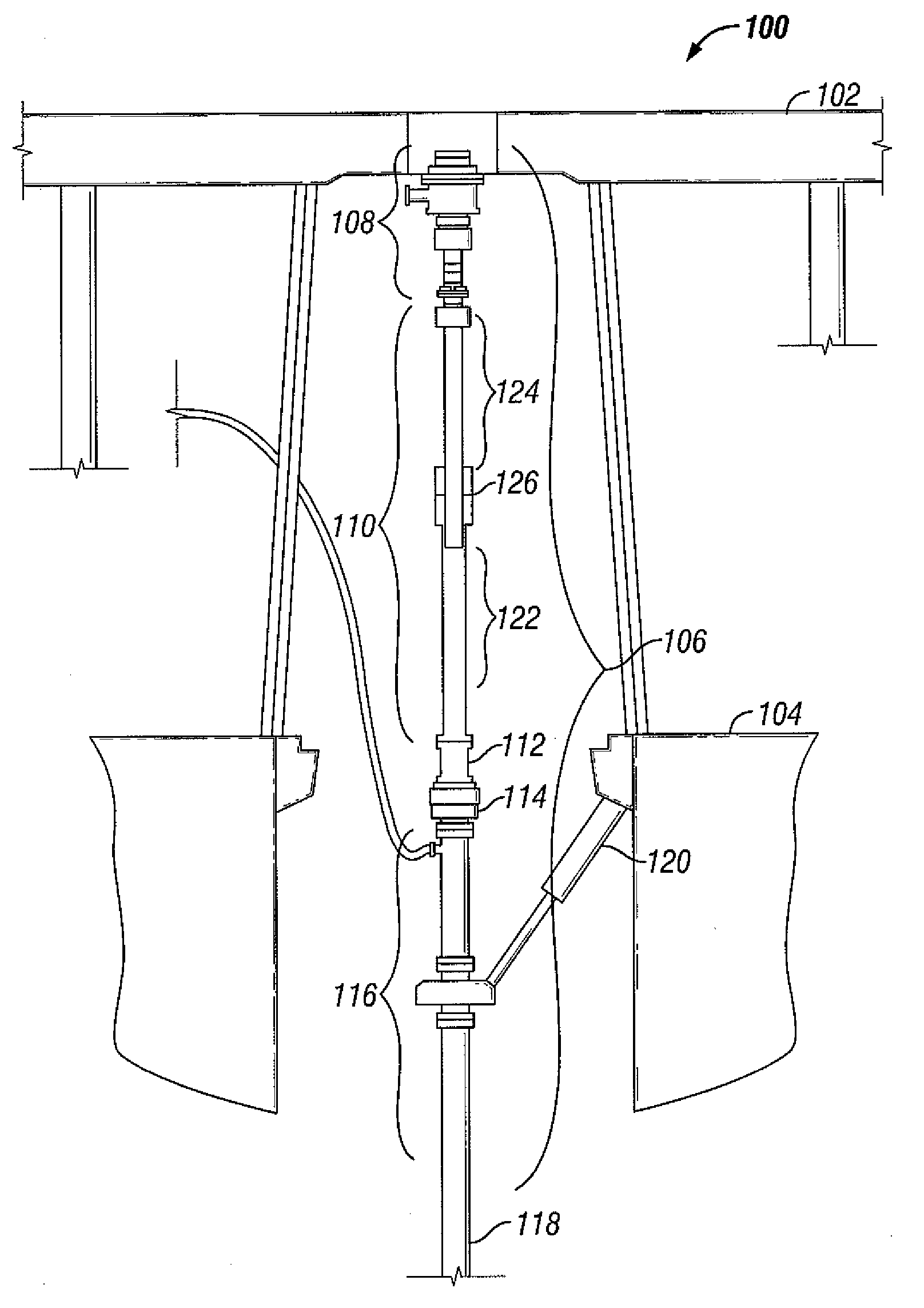
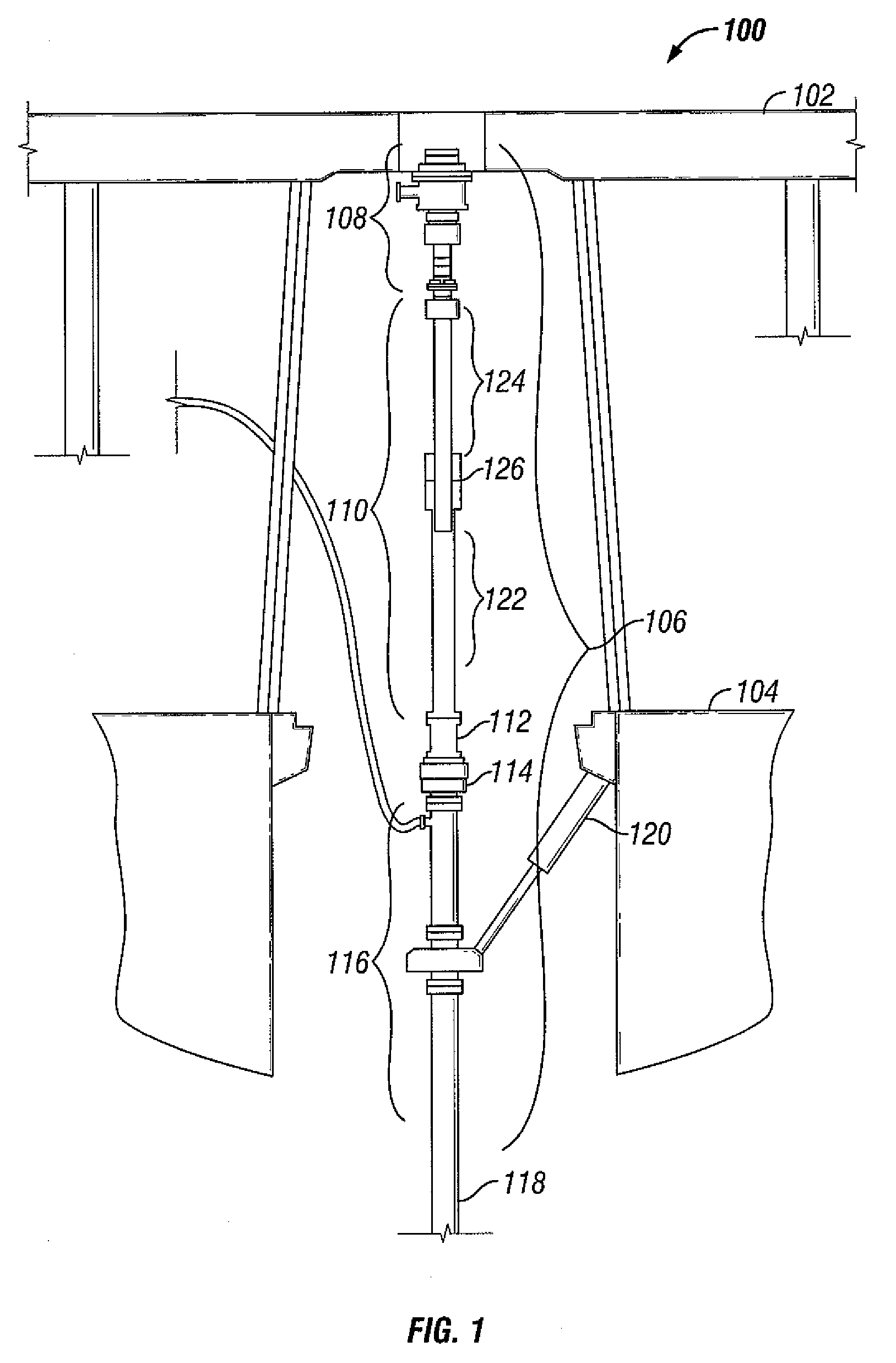
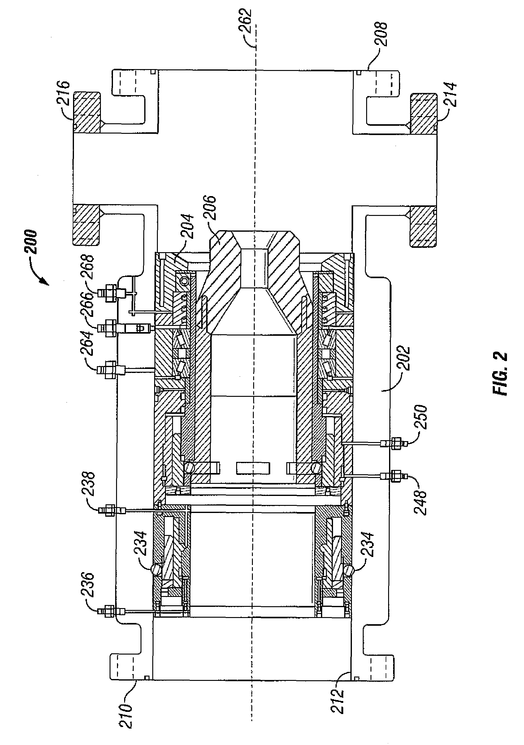
[0032]Selected embodiments of the present disclosure include a rotating control device and its use to isolate a lower portion of a drilling riser from an upper portion of a drilling riser. Particularly, the rotating control device may be useful in managed pressure drilling MPD operations where fluids in the annulus of the drilling riser are pressurized over their normal hydrostatic (i.e., their weight) pressure in an effort to more effectively control drilling conditions in a subsea well. In selected embodiments, the rotating control device enables a drillstring engaged therethrough to be rotated and tripped in or out of the wellbore while maintaining the seal between the upper portion and the lower portion of the drilling riser. Furthermore, selected embodiments of the present disclosure include a rotating control device whereby the seal apparatus thereof is retrievable therefrom without disconnecting any portion of the drilling riser.

[0033]Referring now to FIG. 1, a portion of an ...


PUM


Abstract

A riser assembly includes a rotating control housing connected between an upper portion and a lower portion of a riser assembly, and a packing element rotatable with respect to the rotating control housing, wherein the packing element is configured to isolate an annulus of the lower portion from the upper portion when a drillstring is engaged through the packing element, and wherein the packing element is configured to be retrieved and replaced through the upper portion.

Description

BACKGROUND[0001]1. Field of the Disclosure[0002]The present disclosure generally relates to apparatus and methods for managed pressure drilling. More particularly, the present disclosure relates to apparatus and methods to drill subsea wellbores offshore through drilling risers in managed pressure drilling operations. More particularly still the present disclosure relates to apparatus and methods including rotating control devices having packing elements retrievable through upper portions of drilling risers.[0003]2. Background Art[0004]Wellbores are drilled deep into the earth's crust to recover oil and gas deposits trapped in the formations below. Typically, these wellbores are drilled by an apparatus that rotates a drill bit at the end of a long string of threaded pipes known as a drillstring. Because of the energy and friction involved in drilling a wellbore in the earth's formation, drilling fluids, commonly referred to as drilling mud, are used to lubricate and cool the drill b...

Claims


Application Information

Patent Timeline
Patent Type & Authority Patents(United States)
IPC IPC(8): E21B17/01
CPCE21B33/085E21B17/01
Inventor MAY, JAMESSHELTON, JAYE
Owner SMITH INT INC
Why Eureka
Try Eureka