
Liquid storage container

a liquid storage container and liquid storage technology, applied in printing, other printing apparatus, etc., can solve problems such as the breakdown of the recording head, and achieve the effect of reducing the amount of remaining ink and increasing the space occupied by the air layer in the ink storage chamber

Inactive Publication Date: 2010-04-20
SEIKO EPSON CORP
View PDF55 Cites 17 Cited by
  • Summary
  • Abstract
  • Description
  • Claims
  • Application Information

AI Technical Summary

Benefits of technology

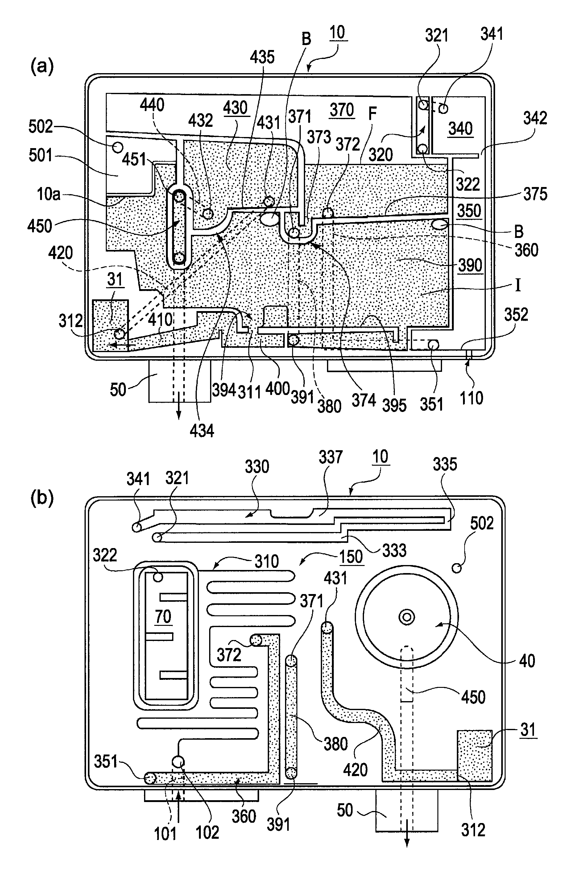
The present invention relates to a liquid storage container for a liquid-consuming apparatus, such as an inkjet printer, that can prevent air bubbles from entering the ink guide path and prevent the liquid remaining-amount sensor from falsely detecting that the ink has run out. The container includes a liquid storage chamber that is detachably attached to the liquid-consuming apparatus, a liquid-supplying unit, and a liquid guide path for guiding the liquid from the storage chamber to the liquid-supplying unit. The container also has an atmosphere communicating path that allows atmospheric air to flow into the storage chamber as the liquid in the chamber is consumed. The technical effects of this invention include preventing air bubbles from entering the ink guide path, preventing the liquid remaining-amount sensor from falsely detecting that the ink has run out, and improving the quality of ink ejection.

Problems solved by technology

If the ink-ejecting operation is performed when there is no more ink in the ink cartridge and no ink can be supplied, the recording head will break down.

Method used


Image

  • Liquid storage container
  • Liquid storage container
  • Liquid storage container

Examples


Embodiment Construction

[0040]A liquid storage container according to a preferred embodiment of the present invention will be described in detail below with reference to the drawings. In the embodiment described below, an ink cartridge that can be attached to and detached from an inkjet recording apparatus (printer), which is an example of a liquid ejection apparatus, will be explained as an example of a liquid storage container.

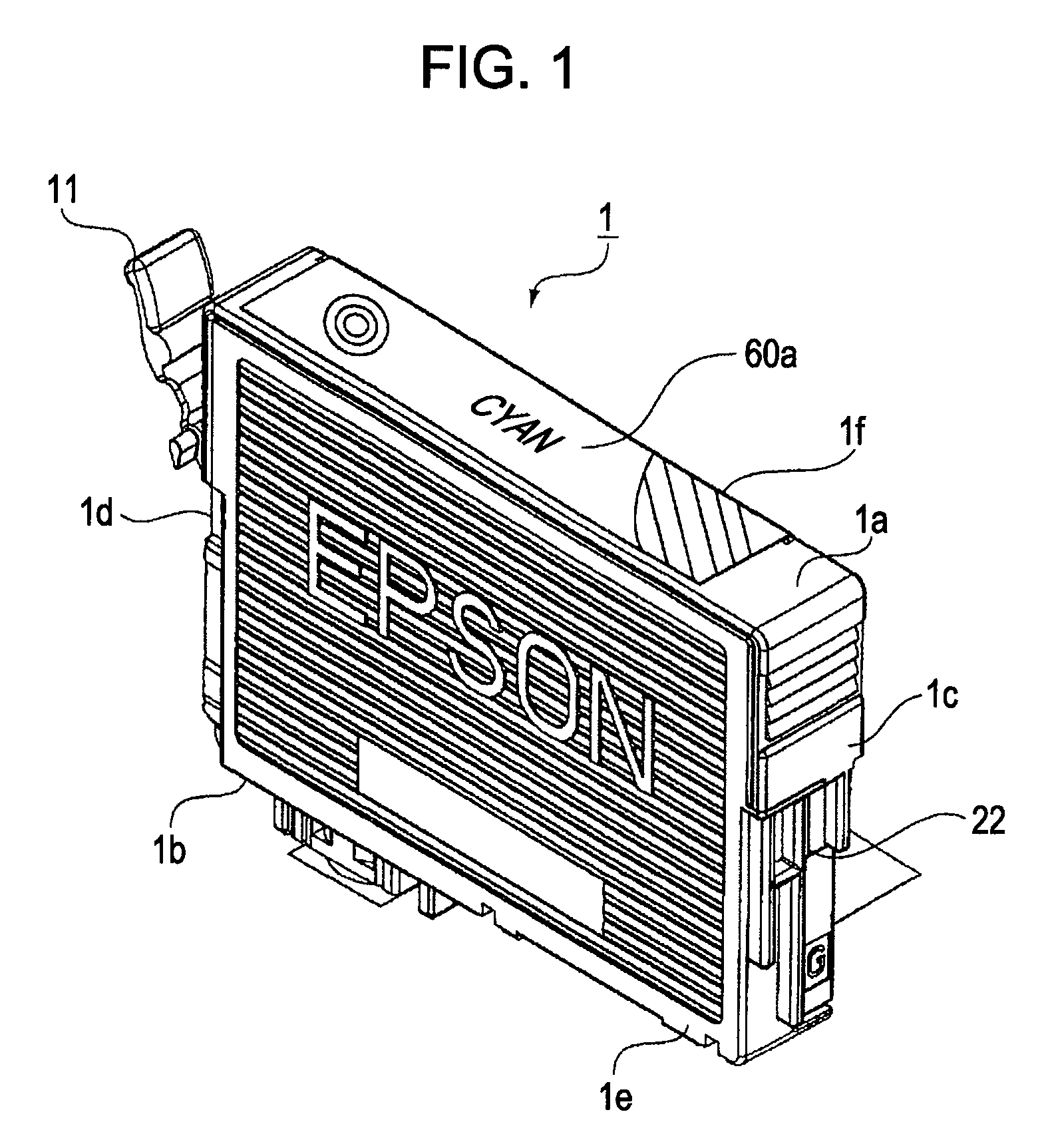
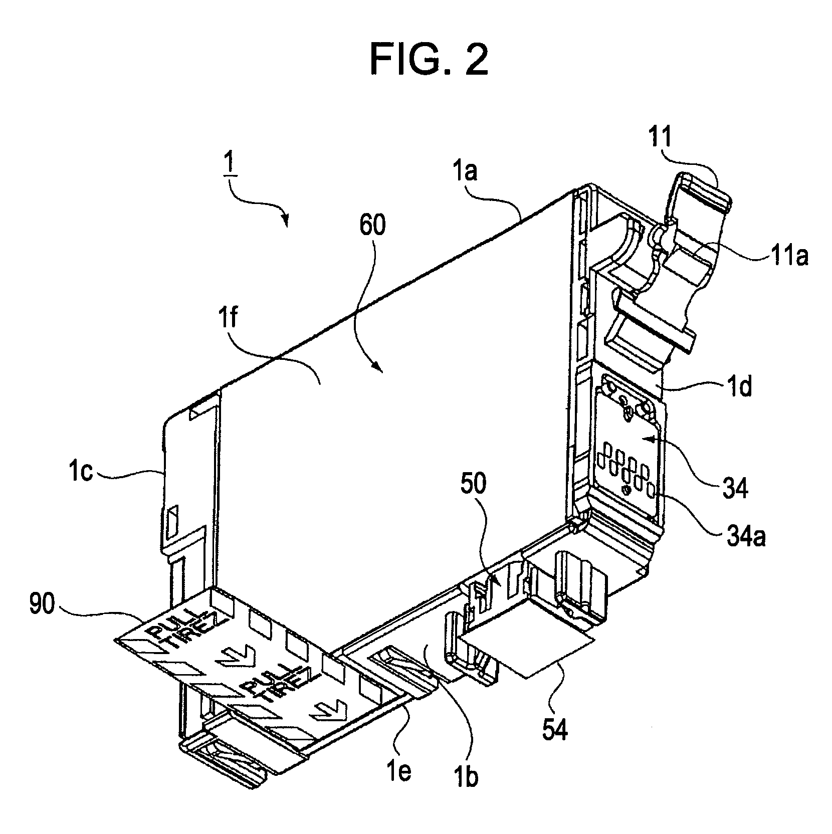
[0041]FIG. 1 is an external perspective view illustrating an ink cartridge as a liquid storage container according to an embodiment of the present invention. FIG. 2 is an external perspective view of the ink cartridge according to the present embodiment shown in FIG. 1 as viewed from the opposite angle. FIG. 3 is an exploded perspective view of the ink cartridge according to the present embodiment. FIG. 4 is an exploded perspective view of the ink cartridge according to the present embodiment shown in FIG. 3 as viewed from the opposite angle. FIG. 5 is a diagram illustrating the st...


PUM


Abstract

To provide a liquid storage container that can prevent false detection of a liquid remaining-amount sensor by preventing air bubbles from reaching a detection position of the liquid remaining-amount sensor as long as a usable amount of liquid remains in liquid storage chambers even when the air bubbles enter liquid guide paths from the liquid storage chambers. The liquid storage container has a cartridge main body 10 that includes an upper ink storage chamber 370, a lower ink storage chamber 390, and a buffer chamber 430. The upper ink storage chamber 370 and the lower ink storage chamber 390 are connected to each other with an ink guide path 380 which provides a descending connection so that ink I descends downward therethrough. The lower ink storage chamber 390 and the buffer chamber 430 are connected to each other with an ink guide path 420 which provides an ascending connection so that the ink I ascends upward therethrough. Thus, the descending connection and the ascending connection are alternately provided so as to connect the ink storage chambers in series.

Description

TECHNICAL FIELD[0001]The present invention relates to a liquid storage container having a container main body that is detachably attached to a liquid-consuming apparatus and supplying liquid contained in the container main body to the liquid-consuming apparatus.BACKGROUND ART[0002]An ink cartridge that contains liquid ink and an ink jet recording apparatus (ink jet printer) to which the ink cartridge is exchangeably attached are examples of a known liquid storage container and a known liquid-consuming apparatus, respectively.[0003]The ink cartridge generally has a container main body that is detachably attached to a cartridge-receiving unit of the ink jet recording apparatus. The container main body includes an ink storage chamber that is filled with ink, an ink-supplying unit for supplying the liquid contained in the ink storage chamber to the ink jet recording apparatus, an ink guide path through which the ink storage chamber and the ink-supplying unit communicate with each other,...

Claims


Application Information

Patent Timeline
Patent Type & Authority Patents(United States)
IPC IPC(8): B41J2/175B41J29/393
CPCB41J2/17513
Inventor ISHIZAWA, TAKUSHINADA, SATOSHI
Owner SEIKO EPSON CORP
Learn More