Hydraulic tensioner lifter

a technology of hydraulic tensioner and lifter, which is applied in the direction of mechanical equipment, belts/chains/gearrings, and mechanical equipment, etc., can solve the problems of excessive tension on the endless transmission belt, noise generation, and time-consuming, and achieves small resistance, reduced noise generation, and increased capacity

Inactive Publication Date: 2010-04-20
HONDA MOTOR CO LTD
View PDF10 Cites 43 Cited by
  • Summary
  • Abstract
  • Description
  • Claims
  • Application Information

AI Technical Summary

Benefits of technology

[0016]According to an embodiment of the present invention, when the plunger is extremely projecting, the total spring length of the series of springs is longer and the spring constant of the series of springs is smaller than any of the spring constants of the individual springs. Therefore, the tensioner lifter softly bears the pushing force from the endless transmission belt in response to a change in the tension of the endless transmission belt in a plunger projecting condition, so that the endless transmission belt is stably held in place. Thus, the generation of a large tension on the endless transmission belt is prevented, thereby improving the durability of the endless transmission belt.
[0023]According to an embodiment of the present invention, since the tip of the conical valve disc of the relief valve or the relief valve body projects towards the first oil channel and the second oil channel, the position of the valve disc in the relief valve can be visually checked easily and properly.

Problems solved by technology

Therefore, when the engine is started, it takes some time to remove the air from the oil circuit of the hydraulic tensioner lifter and fill the oil circuit with oil.
Also, at the time of start, noise may be generated during transition of the chain from a loose state to a tense state.
If the spring constant of the tensioner spring is increased in order to avoid this, the spring force of the tensioner spring would rapidly grow with an increase in the plunging amount of the plunger, which would cause an excessive force to be applied to the endless transmission belt and thus resulting in an excessive tension on the endless transmission belt.

Method used


Image

  • Hydraulic tensioner lifter
  • Hydraulic tensioner lifter
  • Hydraulic tensioner lifter

Examples


Embodiment Construction

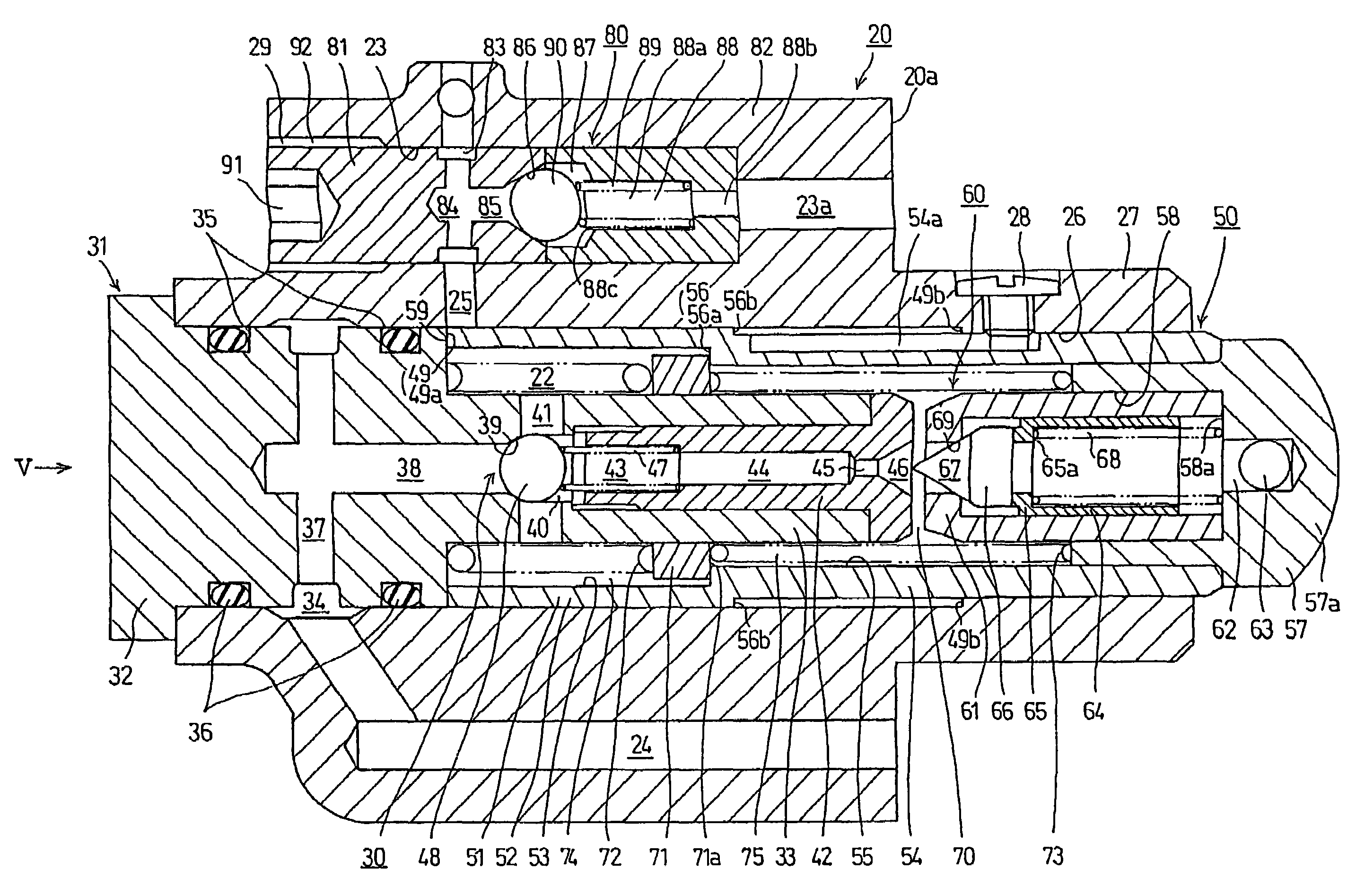
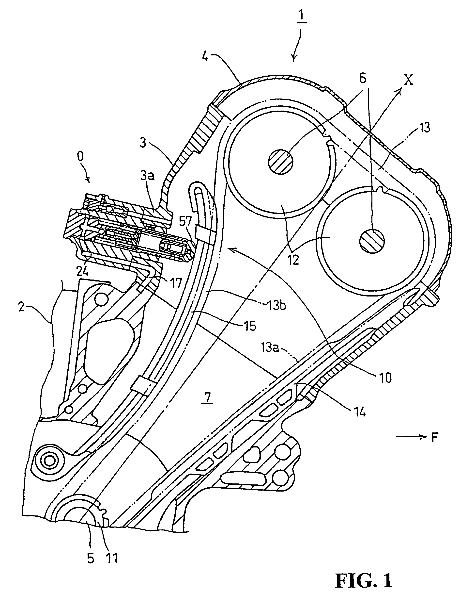
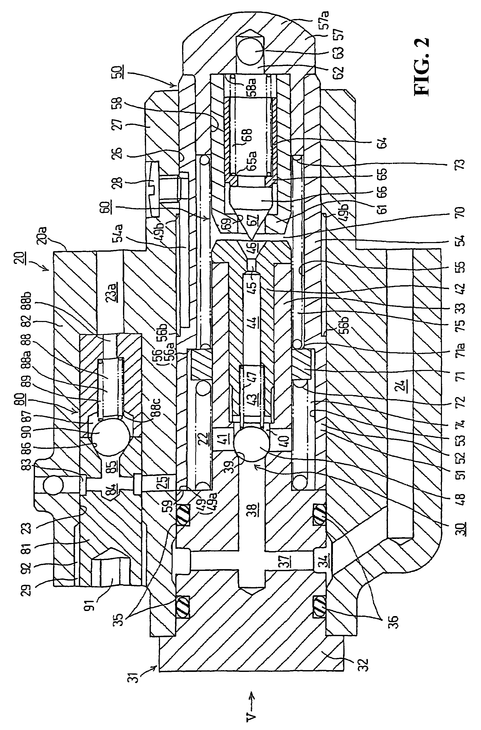
[0037]Next a description will be given of a hydraulic tensioner lifter 0 as an embodiment of the present invention, which is shown in FIGS. 1 to 6. This hydraulic tensioner lifter 0 is applied to a transmission mechanism 10 of a valve train of a DOHC engine 1. This hydraulic tensioner lifter 0 is mounted on a small vehicle with the centerline X (see FIG. 1) of the cylinder of the hydraulic tensioner lifter 0 inclined toward the front of the body of a small vehicle such as a motorcycle (not shown).

[0038]The above internal combustion engine 1 is a single-cylinder engine or an in-line multi-cylinder engine in which a plurality of cylinders are arranged in parallel in the vehicle width direction at regular intervals where in a cylinder block 2 of the engine 1, a crankshaft 5 is supported in a manner that it can rotate clockwise as viewed in FIG. 1, and a cylinder head 3 and a head cover 4 are laid over the top face of the cylinder block 2 in sequence. The cylinder block 2, cylinder head...


PUM


Abstract

To provide an adequate biasing load to an endless transmission belt by biasing forces of a plurality of springs with different biasing forces and oil pressure biasing force to permit an easy adjustment. In a structure which includes an almost cylindrical plunger, a tensioner body into which the plunger is fitted, high pressure oil chambers are formed by the tensioner body and the plunger and supplied with oil pressure. Two tensioner springs, a rigid spring and a soft spring are supported by the tensioner body and are arranged in series for biasing the plunger. The plunger in its fully stretched state is supported by the serially arranged rigid and soft tensioner springs. In a condition when the plunger is pushed back from this fully stretched state by a prescribed amount or further, the plunger is supported by the rigid tensioner spring.

Description

CROSS-REFERENCE TO RELATED APPLICATIONS[0001]The present non-provisional application claims priority under 35 USC 119 to Japanese Patent Application No. 2004-270953 filed on Sep. 17, 2004 the entire contents thereof is hereby incorporated by reference.BACKGROUND OF THE INVENTION[0002]1. Field of the Invention[0003]The present invention relates to a hydraulic tensioner lifter which applies tension to an endless transmission belt such as a chain or belt used in the transmission mechanism of an internal combustion engine.[0004]2. Description of Background Art[0005]Conventionally, in an internal combustion engine, a hydraulic tensioner lifter has been used in order to apply tension to an endless transmission belt used in the transmission mechanism, such as a chain. This hydraulic tensioner lifter uses a method which pushes a plunger by means of tensioner spring and oil pressure, where as the plunger stretches, a stretched lifter gives the chain a prescribed tension to suppress oscillati...

Claims


Application Information

Patent Timeline
Patent Type & Authority Patents(United States)
IPC IPC(8): F16H7/08
CPCF16H7/0836F16H2007/0806F16H2007/0859F16H2007/0814F16H2007/0812
Inventor EMIZU, OSAMUSAKAI, TAKESHIFURUYA, MASASHI
Owner HONDA MOTOR CO LTD
Why Eureka
Try Eureka