Staple container for electric stapler

a technology of electric staplers and staple containers, which is applied in the field of staple container refills for electric staplers, can solve the problems of reducing the elastic force of the spring and the spring load, and achieves the effect of reducing the driving load of the staple pushing plate and preventing the staple container from being erroneously removed

Active Publication Date: 2010-04-27
MAX CO LTD
View PDF12 Cites 12 Cited by
  • Summary
  • Abstract
  • Description
  • Claims
  • Application Information

AI Technical Summary

Benefits of technology

[0016]In accordance with one or more embodiments of the present invention, in a staple container, on the inner wall of the case in which stacked stapled sheets each composed of linear staples are loaded, nonreturn projections are provided. A nonreturn lug is attached to the staple pushing plate for holding down the upper face of the staple sheets within the case using a spring. The nonreturn lug is engaged with the nonreturn projections to inhibit the ascent of the staple pushing plate. In addition, the height of the apex of the nonreturn projection is lowered from top to bottom. Thus, as the staple pushing plate descends, the descending driving load of the staple pushing plate is reduced. As a result, even if the elastic force of the spring which depresses the staple pushing plate is reduced, the staple pushing plate can be surely lowered to the bottom of the case, thereby holding the staple sheets within the case.
[0017]Further, in accordance with one or more embodiments of the present invention, when the staple pushing plate reaches the bottom of the staple container, the staple pushing plate is slid forward; when the case is loaded in the container accommodating chamber, the engagement portion is engaged with the side of the container accommodating chamber; and when the staple pushing plate moves forward, pivoting of the rear wall is permitted, thereby releasing engagement of the engagement portion. Therefore, if the staple sheets remain within the case, the staple container cannot be removed from the container accommodating chamber. On the other hand, if no staple sheets remain within the case, the staple container can be removed from the container accommodating chamber. As a result, it is possible to prevent the staple container from being erroneously removed although the staple sheets remain.

Problems solved by technology

However, in this case, since depressing of the plate-shaped pushing member while the electric stapler is used is entrusted to a spring on a side of a staple magazine or a stapler body, as the staple sheets are consumed and the plate-shaped pushing member descends, a load of the spring decreases so that an elastic force of the spring is problematically reduced.

Method used


Image

  • Staple container for electric stapler
  • Staple container for electric stapler
  • Staple container for electric stapler

Examples


embodiment 1

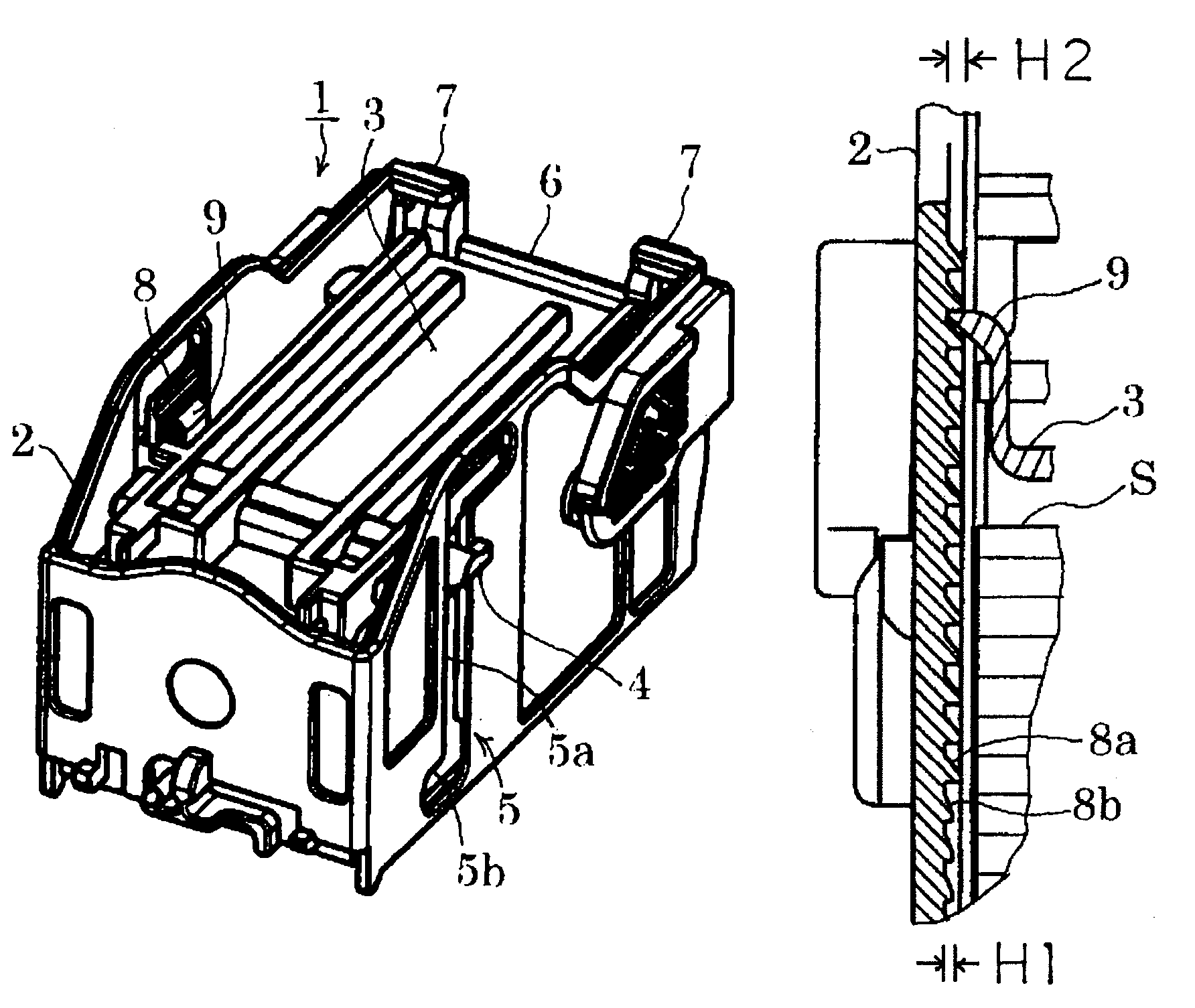
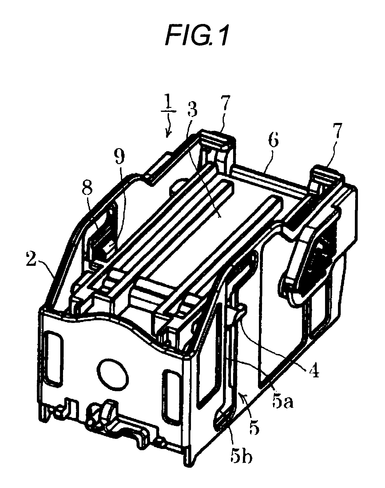
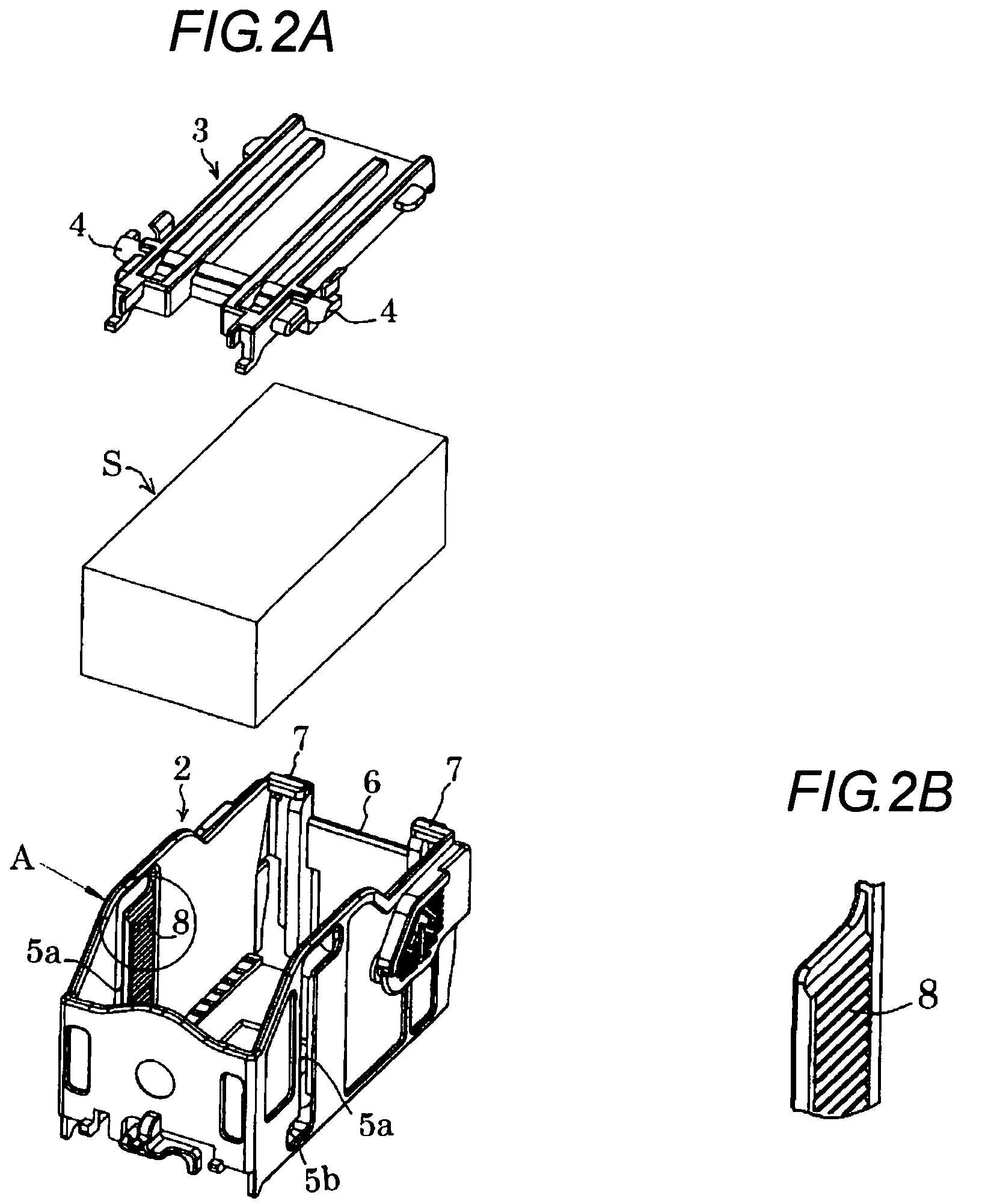
[0042]FIG. 1 to FIG. 3E illustrate a staple container 1. Within a square case 2 with an upper face opened, a staple pushing plate 3 is loaded so as to overlie an upper face of stacked staple sheets S.

[0043]As shown in FIG. 2A, the staple pushing plate 3 has a guide shaft 4 which projects outwardly from both right and left sides at its front. On right and left side walls of the case 2, vertical guide grooves 5 in which the guide shaft 4 of the staple pushing plate 3 is engaged are formed. The guide groove 5 horizontally bends at both upper and lower ends of a vertical groove portion 5a. Thus, when the staple pushing plate 3 descends along the guide grooves 5 to reach the bottom of the case 2, the staple pushing plate 3 can be slid forward along the horizontal groove portions 5b of the guide grooves 5.

[0044]A rear wall 6 of the case 2 is coupled with the case 2 through thin hinges 7 at the upper end. By pushing the rear wall 6 from back, the rear wall 6 can be pivoted forward. As show...


PUM


Abstract

From top to bottom of an inner wall of a case in which stacked stapled sheets each composed of linear staples connected in parallel are accommodated, horizontal nonreturn projections are successively arranged. A nonreturn lug is attached to a staple pushing plate pushing the staple sheets by a spring, and the nonreturn lug is engaged with the nonreturn projections of the case. The nonreturn lug and the nonreturn projections are shaped to permit a descent of the staple pushing plate and inhibit an ascent thereof. In addition, a height of an apex of each of the nonreturn projections is reduced step-wise or with no step from top to bottom of the inner wall of the case.

Description

TECHNICAL FIELD[0001]The present invention relates to a staple container for refill for an electric stapler, and more particularly to a staple container for an electric stapler with an improved pushing mechanism for staple sheets within a case of the staple container.BACKGROUND ART[0002]An electric stapler in which stacked staple sheets each composed of linear staples connected in parallel are loaded is used as not only a stand-alone stapler but also incorporated in a copier or post-printing processor.[0003]As a kind of electric stapler, there has been proposed an electric stapler using a staple magazine in which stacked staple sheets are loaded. In this electric stapler, when the staples are used up, an entire magazine is replaced. JP-A-2004-237446 discloses an electric stapler in which for the purpose of resource-saving, a staple for refill is received within a case of plastic paper, and the case is loaded in a staple magazine or an electric stapler body.[0004]The staple for refil...

Claims


Application Information

Patent Timeline
Patent Type & Authority Patents(United States)
IPC IPC(8): B25C5/06
CPCB27F7/38B25C7/00B25C5/16B25C5/1606
Inventor HARAMIISHI, KIICHIMORII, KOJI
Owner MAX CO LTD
Why Eureka
Try Eureka