Liquid supply device, liquid ejecting apparatus, and liquid supply method

a liquid supply device and liquid ejecting technology, applied in printing and other directions, can solve the problems of ink hardening, dust sticking, ink hardening, etc., and achieve the effect of reducing the viscosity of ink, and reducing the volume of ink

Active Publication Date: 2012-04-03
SEIKO EPSON CORP
View PDF21 Cites 6 Cited by
  • Summary
  • Abstract
  • Description
  • Claims
  • Application Information

AI Technical Summary

Benefits of technology

[0008]An advantage of some aspects of the invention is that it provides a liquid supply device, which can apply a pressure to a liquid supply channel so as to cause a liquid to quickly flow from an upstream side as a liquid supply source side toward a downstream side in a state where a valve provided in the liquid supply channel is closed, and in this state, even if the valve is open, can prevent the liquid from being wastefully supplied to the downstream side and consumed. Another advantage of some aspects of the invention is that it provides a liquid ejecting apparatus including the liquid supply device, and a liquid supply method.
[0010]With this configuration, if the downstream-side second valve is open, the upstream-side first valve is closed to close the liquid supply channel. For this reason, in a state where the valve provided on the downstream side in the liquid supply channel is closed, the pressure is applied to the liquid supply channel so as to cause the liquid to quickly flow from the upstream side as the liquid supply source side toward the downstream side. In this state, even if the valve is open, the liquid supply to the downstream side is suppressed by the closed first valve on the upstream side. Therefore, wasteful consumption of the liquid in the liquid supply source can be suppressed.
[0014]With this configuration, when the pump performs a pump action to supply the liquid, the displacement member is configured to be displaced against the urging force of the urging member only if the pump performs one of a suction action and an ejection action. Otherwise, the displacement member is displaced to an original state by the urging force of the urging member. Therefore, a drive load of the pump can be reduced.
[0020]With this configuration, when the liquid ejecting apparatus performs so-called choke cleaning in which, while the negative pressure is applied to the liquid supply channel through the liquid ejecting head, and the valve provided in the liquid supply channel is switched from the valve close state to the valve open state, thereby forcibly discharging the liquid from the liquid ejecting head, wasteful consumption of the liquid can be suppressed.
[0021]According to yet another aspect of the invention, a liquid supply method for a liquid supply device includes, in a state where, when a first valve and a second valve are provided in a liquid supply channel, through which a liquid is supplied from an upstream side as a liquid supply source side toward a downstream side, to open and close the liquid supply channel, and the second valve on a downstream side from the first valve is closed, applying pressure to the liquid supply channel so as to cause the liquid to quickly flow from the upstream side toward the downstream side, and when the second valve is opened to supply the liquid on an upstream side from the second valve to a downstream side, closing the first valve. With this configuration, the same effects as the above-described liquid supply device can be obtained.
[0024]With the above-described configuration, first, if the pump performs the suction action, the pressure in the pump chamber decreases, and the second valve on the downstream side from the pump is closed. In the valve close state, the negative pressure is applied to the liquid supply channel from the downstream side. That is, if the negative pressure in the liquid supply channel increases, the second valve is reliably closed, and the liquid in the pump chamber can be prevented from flowing out into the liquid supply channel on the downstream side. In addition, after the second valve is closed, if the pump performs the ejection action, the second valve is opened by the ejection pressure from the pump chamber, and ink flows into the liquid supply channel. As a result, choke cleaning can be performed with a small amount of ink consumption.

Problems solved by technology

In this printer, if an ink solvent evaporates from the nozzle of a recording head serving as a liquid ejecting head, an increase in ink viscosity, ink hardening, or dust sticking may occur.
The increase in ink viscosity, ink hardening, or dust sticking may cause clogging in the nozzle.
In addition, air bubbles may enter the recording head from the nozzle, and defective printing may be caused.
Accordingly, in this printer, during choke cleaning, a large amount of ink is wastefully consumed.
As a result, ink is wastefully consumed until the second valve is closed.

Method used


Image

  • Liquid supply device, liquid ejecting apparatus, and liquid supply method
  • Liquid supply device, liquid ejecting apparatus, and liquid supply method
  • Liquid supply device, liquid ejecting apparatus, and liquid supply method

Examples


Embodiment Construction

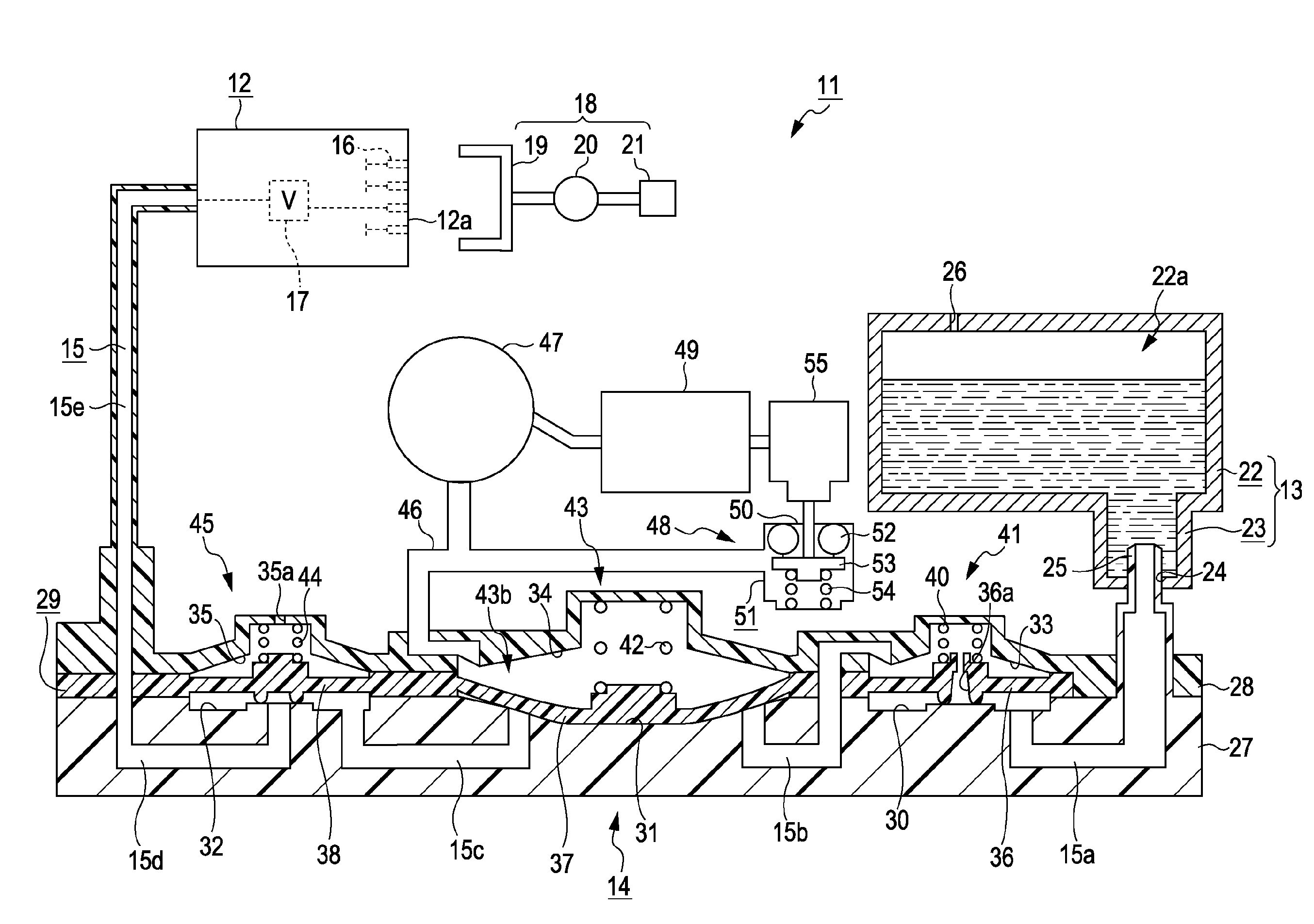
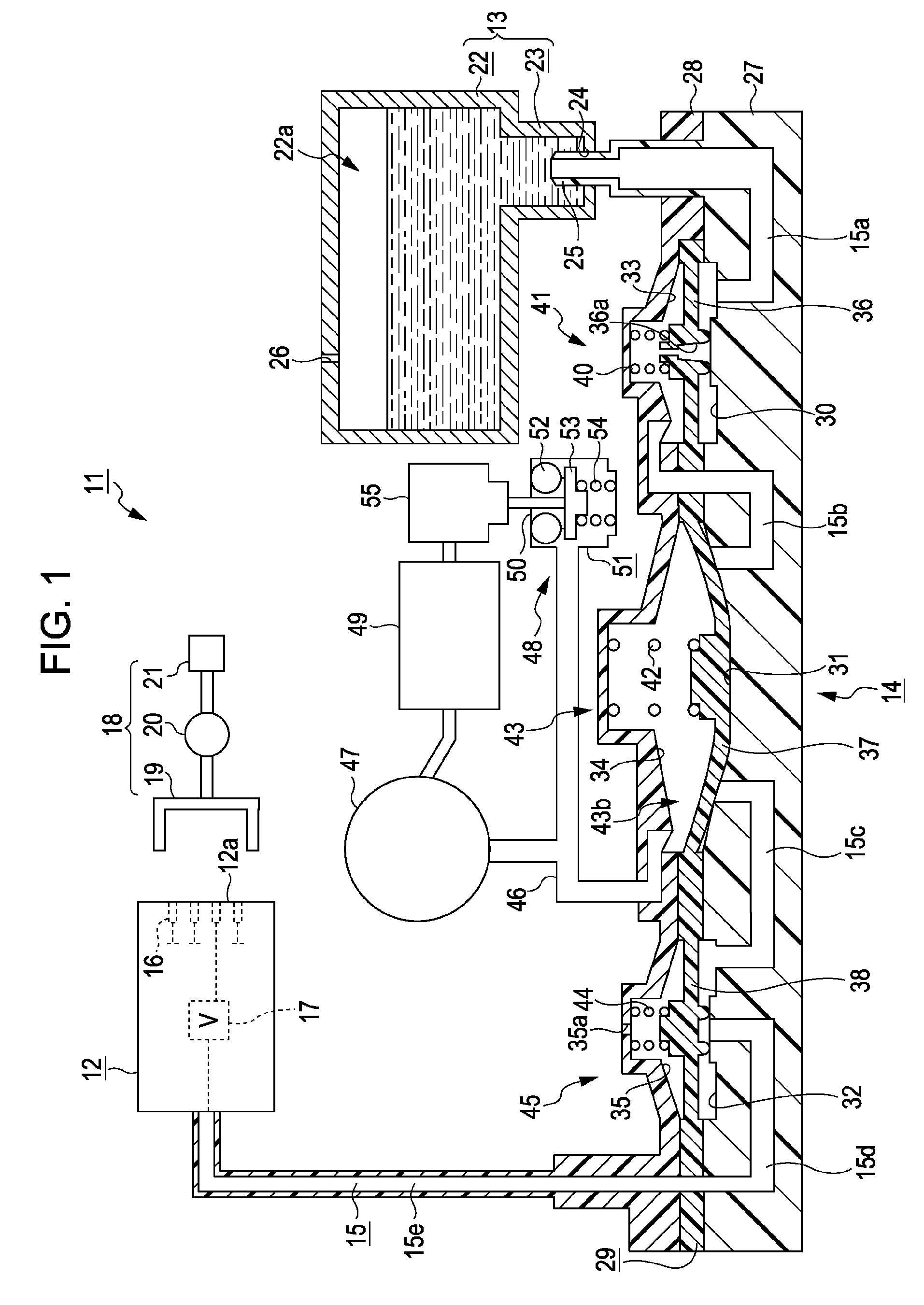
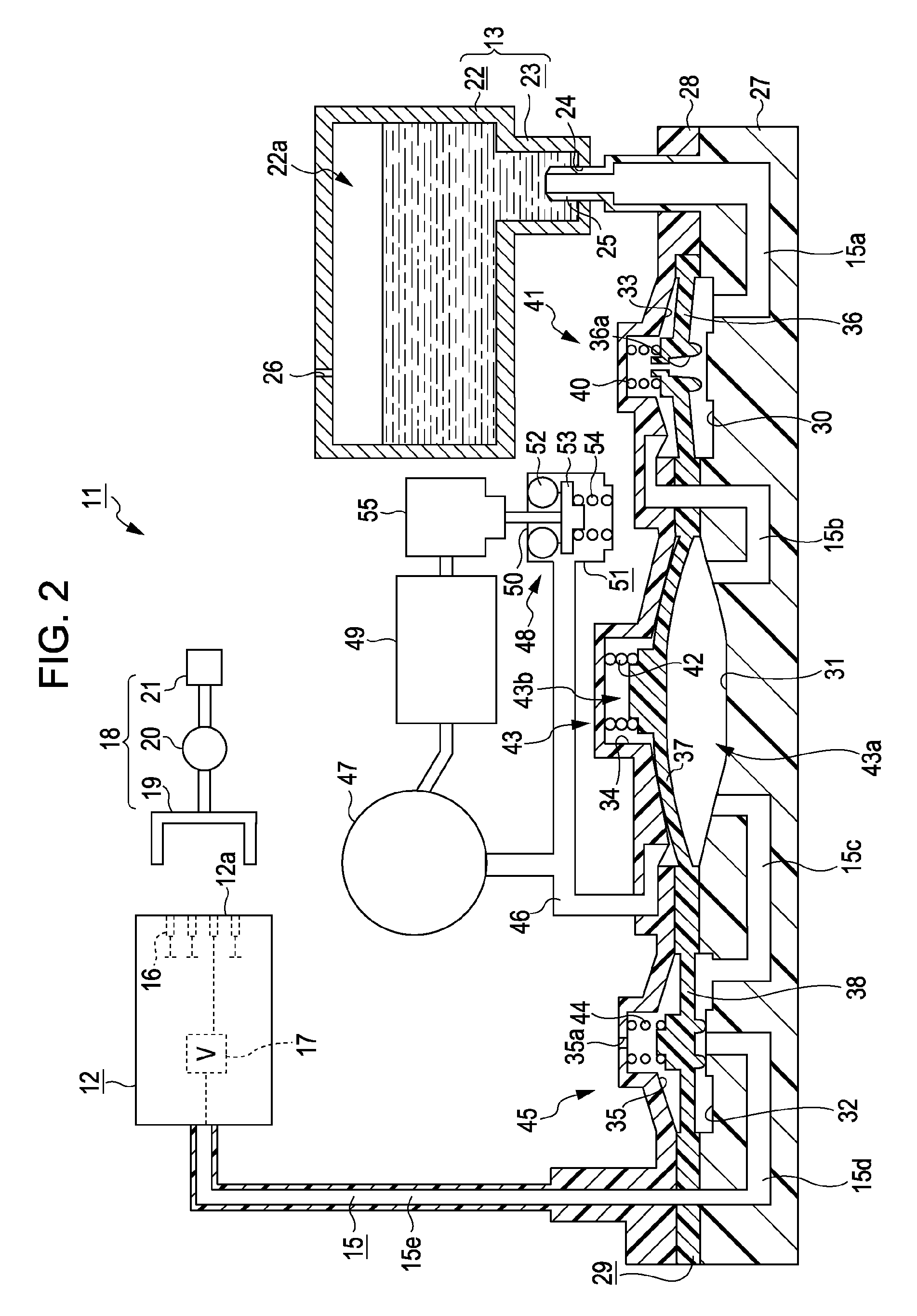
[0029]Hereinafter, an embodiment in which the invention is applied to an ink jet recording apparatus (hereinafter, referred to as “printer”), which is a kind of liquid ejecting apparatus, will be described with reference to FIGS. 1 to 3.

[0030]As shown in FIG. 1, a printer 11 of this embodiment includes a recording head 12 serving as a liquid ejecting head that ejects ink (liquid) onto a target (not shown), and an ink supply device 14 serving as a liquid supply device that supplies, to the recording head 12, ink contained in an ink cartridge 13 serving as a liquid supply source. An ink flow channel (liquid supply channel) 15 is provided through which ink is supplied from an upstream side toward a downstream side, that is, from the ink cartridge 13 toward the recording head 12, in a state where an upstream end of the ink supply device 14 is connected to the ink cartridge 13, and a downstream end of the ink supply device 14 is connected to the recording head 12.

[0031]The printer 11 inc...


PUM


Abstract

A liquid supply device includes a liquid supply channel that supplies a liquid from an upstream side as a liquid supply source side to a downstream side, on which the liquid is consumed, a first valve that is provided in the liquid supply channel to open and close the liquid supply channel, and a second valve that is provided on a downstream side from the first valve in the liquid supply channel to open and close the liquid supply channel. The first valve is closed when the second valve is open.

Description

[0001]The entire disclosure of Japanese Patent Application No. 2007-319816, filed Dec. 11, 2007 and Japanese Patent Application No. 2008-222048, filed Aug. 29, 2008, are expressly incorporated herein by reference.BACKGROUND[0002]1. Technical Field[0003]The present invention relates to a liquid supply device, a liquid ejecting apparatus, and a liquid supply method.[0004]2. Related Art[0005]An ink jet printer (hereinafter, simply referred to as “printer”) is a known example of a liquid ejecting apparatus that ejects a liquid onto a target from a liquid ejecting head. In this printer, if an ink solvent evaporates from the nozzle of a recording head serving as a liquid ejecting head, an increase in ink viscosity, ink hardening, or dust sticking may occur. The increase in ink viscosity, ink hardening, or dust sticking may cause clogging in the nozzle. In addition, air bubbles may enter the recording head from the nozzle, and defective printing may be caused.[0006]Accordingly, as describe...

Claims


Application Information

Patent Timeline
Patent Type & Authority Patents(United States)
IPC IPC(8): B41J2/175
CPCB41J2/175B41J2/17596
Inventor YOKOUCHI, HIDEYA
Owner SEIKO EPSON CORP
Why Eureka
Try Eureka