Barrel polishing method and barrel polishing apparatus

a barrel and polishing technology, applied in the direction of edge grinding machines, grinding machine components, manufacturing tools, etc., can solve the problems of reducing the frictional force between the workpiece and the media, reducing the mass amount, and gradually worn media, so as to reduce the load of the driving motor, reduce the frictional force, and improve the polishing capability

Inactive Publication Date: 2006-06-01
SINTOKOGIO LTD
View PDF5 Cites 5 Cited by
  • Summary
  • Abstract
  • Description
  • Claims
  • Application Information

AI Technical Summary

Benefits of technology

[0005] It is an object of the present invention to provide a flow barrel polishing method and a barrel polishing apparatus that can solve the above-stated conventional disadvantages, that can avoid a reduction in a polishing capability following progress of polishing, and that can greatly improve the polishing capability as compared with that of the conventional polishing method or apparatus.
[0006] The inventors of the present invention exerted their utmost efforts for solving the conventional disadvantages. As a result, the inventors discovered that the polishing capability can be considerably enhanced as compared with the conventional polishing capability by controlling a flow of a mass rising along an inner wall of a polishing bath using an appropriate means against a conventional common knowledge that the polishing capability of the flow barrel polishing is deteriorated when a natural flow of the mass is disturbed. Further, a change in the polishing capability of the flow barrel polishing apparatus appears as a change in a work amount transmitted from the rotary disc to the mass, that is, appears as a change in a rotation resistance of the rotary disc. It is, therefore, possible to grasp the change in the polishing capability of the apparatus as a load of a driving motor for the rotary disc from outside. Accordingly, by controlling the flow of the mass to keep the load of the driving motor for the rotary disc constant, the polishing capability deteriorated as the polishing progresses can be kept constant.
[0011] According to the present invention, the load range of the driving motor for the rotary disc is set in advance as a load current or the like, and the flow area of the mass within the polishing bath is controlled with the load of the driving motor used as a parameter if the load of the driving motor is out of the set range, whereby the mass is polished within the load set range. A deterioration in polishing capability following progress of the polishing can be detected as a reduction in the load of the driving motor for the rotary disc as a result of a reduction in the frictional force between the workpiece and the media due to a reduction in a volume of the mass after wearing of the media or polishing of the workpiece. Therefore, if the load is reduced, then the flow area of the mass within the polishing bath is narrowed to keep the frictional force between the workpiece and the media constant, and the load of the driving motor is always kept within the set range, whereby the barrel polishing can be performed while keeping the polishing capability constant. Besides, by area control of the flow of the mass within the polishing bath, the frictional force between the workpiece and the media can be considerably intensified as compared with that of the conventional method or apparatus. While these advantages of the present invention are conspicuous particularly in dry barrel polishing, they are similarly exhibited even in wet barrel polishing.

Problems solved by technology

The conventional flow barrel polishing has, however, disadvantages in that the media is gradually worn as the polishing progresses, a mass amount is reduced, a frictional force between the workpiece and the media is reduced, and a deterioration in a polishing capability is thereby unavoidable.
These disadvantages are conspicuous particularly in dry flow barrel polishing.

Method used


Image

  • Barrel polishing method and barrel polishing apparatus
  • Barrel polishing method and barrel polishing apparatus
  • Barrel polishing method and barrel polishing apparatus

Examples


first embodiment

Movable Means and Elevation Mechanism

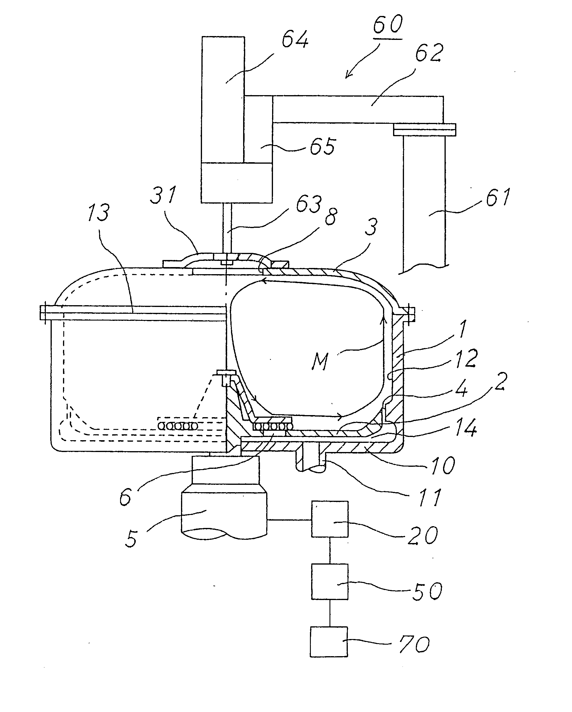
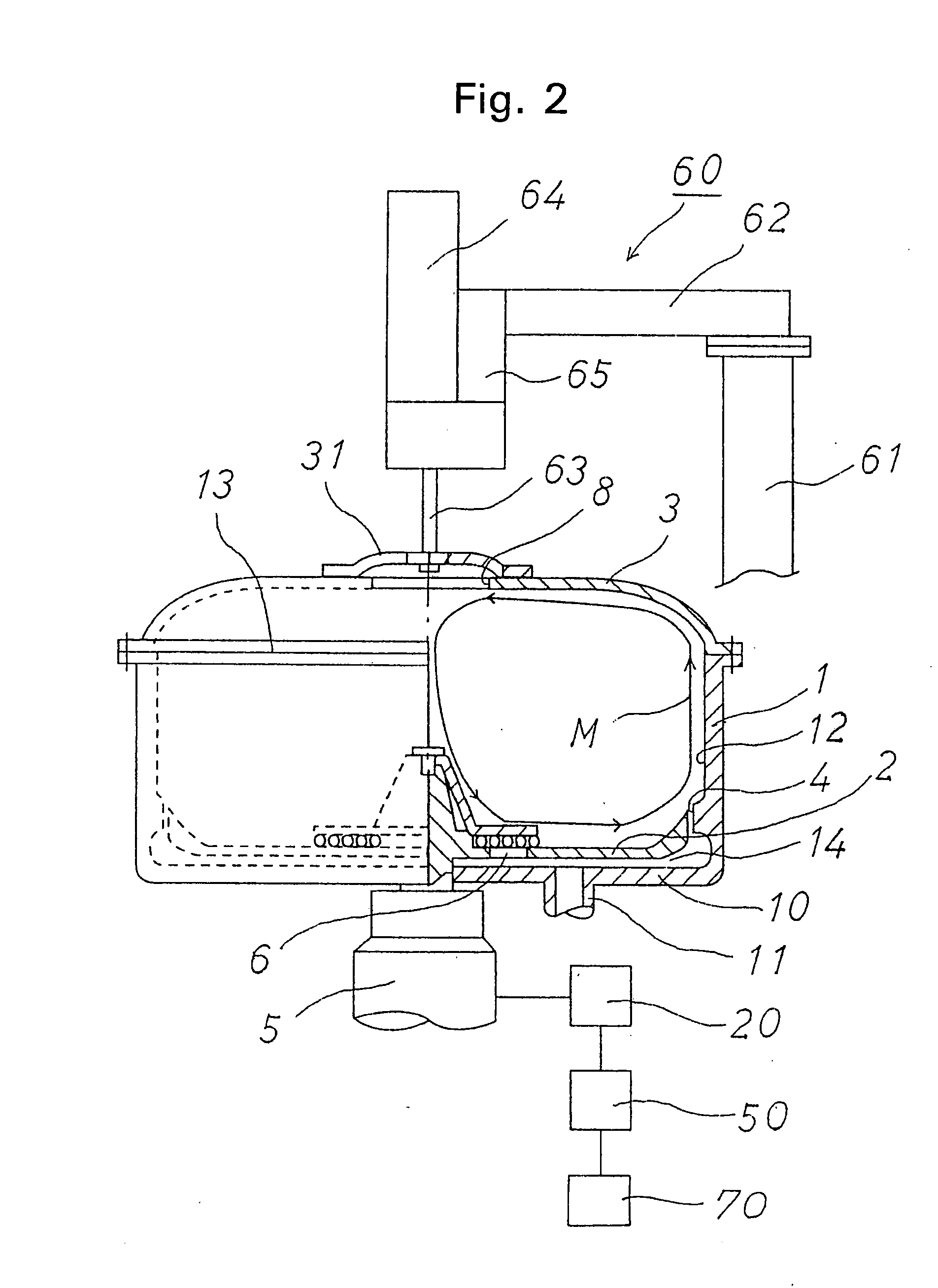
[0026]FIG. 2 depicts a dry flow barrel polishing apparatus according to a first embodiment of the present invention. In FIG. 2, reference number 1 depicts a polishing bath into which a mass M configured by a workpiece and a media is input, and 2 denotes a plate-like rotary disc provided on a bottom of the polishing bath. The rotary disc 2 has a peripheral edge curved upward so that the mass M can easily flow upward. An antifriction lining consisting of urethane rubber or the like is applied to a portion in which the polishing bath 1 contacts with the mass M on the rotary disc 2. Reference 3 denotes a movable means that consists of a flexible material such as rubber for closing an upper opening 13 of the polishing bath 1. According to this embodiment, the movable means 3 is of a lid shape and has a peripheral portion fixed to an upper end of the polishing bath 1. As shown in FIG. 2, the peripheral edge of this movable means 3 is preferably curved...

second embodiment

Modification of Movable Means and Elevation Mechanism

[0036] In the first embodiment, the peripheral edge of the flexible movable means 3 is fixed to the upper end of the polishing bath 1. Alternatively, as shown in FIG. 4, the movable means 3 may consist of a rigid material such as metal, and may be provided so as to be able to be vertically slid within the polishing bath 1 by the elevation mechanism 60 working with the load of the driving motor 20. In this case, an outside diameter of the movable means 3 is set slightly smaller than an inside diameter of the polishing bath 1. In a left half part of FIG. 4, a free flow path of the mass M for the conventional apparatus without the movable means 3 is indicated by a broken line. In this second embodiment, similarly to the first embodiment, the upper portion of the mass M that rotatably flows is suppressed by the movable means 3, the reduced polishing force can be recovered.

third embodiment

Movable Means and Pressurization Mechanism for Movable Means

[0037]FIG. 5 depicts a third embodiment of the present invention. In FIG. 5, a movable means 3 having an opening cylinder 32 provided at its center is slidably provided within a polishing bath 1. In addition, an outer cylinder 16 into which this opening cylinder 32 can be slidably fitted is provided on an upper lid 15 of the polishing bath 1. An annular pressure chamber 17 is formed between the upper lid and the movable means 3, and a pressurized fluid such as a compressed air is supplied from a pressurized fluid supply port 18 provided in the upper lid 15 to thereby pressurize the movable means 3 downward.

[0038] In this embodiment, a pressure of the pressurized fluid supplied from the pressurized fluid supply port 18 is increased and the movable means 3 is pressed downward in a piston manner when a load of a driving motor 20 is reduced, thereby controlling a flow area of a mass M. It is thereby possible to increase a fri...


PUM

PropertyMeasurementUnit
diameteraaaaaaaaaa
lengthaaaaaaaaaa
diameteraaaaaaaaaa

Abstract

Barrel polishing is effected while causing a mass (M) consisting of work and media (polishing material) to rotation-flow by rotating a rotary disk installed in the bottom of a polishing tank by a drive motor. A load on the drive motor for the rotary disk is preset as by a load current value, and the flow of the mass (M) in the polishing tank is controlled, thereby effecting polishing while maintaining the load on the drive motor within the preset range.

Description

CROSS REFERENCE TO RELATED APPLICATIONS [0001] This application is a continuation of International Application No. PCT / JP2003 / 011952, filed Sep. 19, 2003, which designated the United States, and also claims the benefit of Japanese Application No. 2002-346870, filed Nov. 29, 2002, the entireties of which are incorporated herein by reference.FIELD OF THE INVENTION [0002] The present invention relates to a flow barrel polishing method and a flow barrel polishing apparatus for polishing a workpiece while causing a mass configured by the workpiece and a media to centrifugally flow in a polishing bath. BACKGROUND OF THE INVENTION [0003] Flow barrel polishing is a method for inputting a mass configured by a workpiece that is a polishing target and a media that is a polishing material into a polishing bath, and for polishing the workpiece while causing the mass to centrifugally flow using a rotary disc provided on a bottom of the polishing bath. One example of the method is disclosed in Jap...

Claims


Application Information

Patent Timeline
Patent Type & Authority Applications(United States)
IPC IPC(8): B24B1/00B24B31/00B24B31/108
CPCB24B31/108
Inventor NISHIMURA, KAZUTOSHIISHIDA, TAKAOMASUDA, YOSHIHIRO
Owner SINTOKOGIO LTD
Why Eureka
Try Eureka