High efficiency constant current LED driver

a constant current led driver, high efficiency technology, applied in the direction of electroluminescent light sources, electric lighting sources, semiconductor lamp usage, etc., can solve the problems of narrow operating frequency range, limited modulation capability of the frequency for the gain, and insufficient frequency rang

Inactive Publication Date: 2011-04-07
INVENTRONICS HANGZHOU
View PDF5 Cites 104 Cited by
  • Summary
  • Abstract
  • Description
  • Claims
  • Application Information

AI Technical Summary

Benefits of technology

[0005]The efficiency of LLC resonant circuit is highest when the operating frequency is close to the resonant frequency, so the normal operating point is always close to resonant frequency. When input voltage increases and output voltage reduces, the larger gain can be obtained by decreasing operating frequency; when the input voltage increases or output voltage reduces, the lower gain can be obtained by increasing operating frequency. But the modulation capability from the frequency for the gain is limited and the range is narrow. Even through the modulation is able to be adjusted, the operating frequency range is too wide and the efficiency is low. Thus, the LLC circuit is difficult to guarantee the high efficiency within the whole output voltage range, when it is used in constant current LED driver with wide output voltage range.
[0027]When the post stage circuits are the Boost converters, the output voltage of the isolated DC / DC converter is always tracking the output voltage of the Boost converter, and the output voltage of DC / DC converter is always slightly higher than the maximum voltage of multiple Boost converters, and it makes the duty cycle of each output operate at close to 100% and which obtains high efficiency. At the same time, the PFC output voltage is also tracking the DC / DC output voltage as above illustrated; the efficiency of the isolated DC / DC converter is also high. Then the efficiency of the whole constant current converter with multiple outputs is optimized with a high efficiency.

Problems solved by technology

But the modulation capability from the frequency for the gain is limited and the range is narrow.
Even through the modulation is able to be adjusted, the operating frequency range is too wide and the efficiency is low.
Thus, the LLC circuit is difficult to guarantee the high efficiency within the whole output voltage range, when it is used in constant current LED driver with wide output voltage range.
Being used in a constant current LED driver with wide output voltage range, when the output voltage is low and the duty cycle is small, the efficiency is low.

Method used


Image

  • High efficiency constant current LED driver
  • High efficiency constant current LED driver
  • High efficiency constant current LED driver

Examples


Embodiment Construction

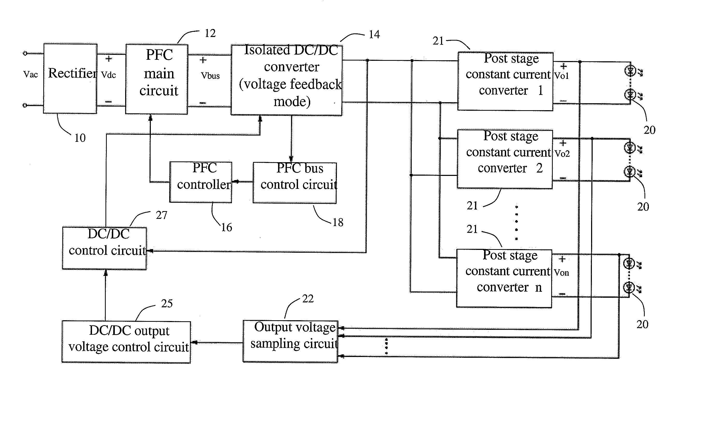
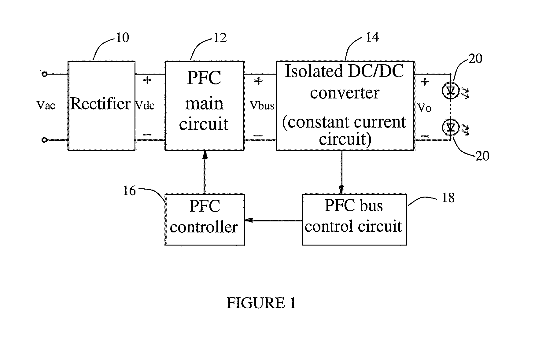
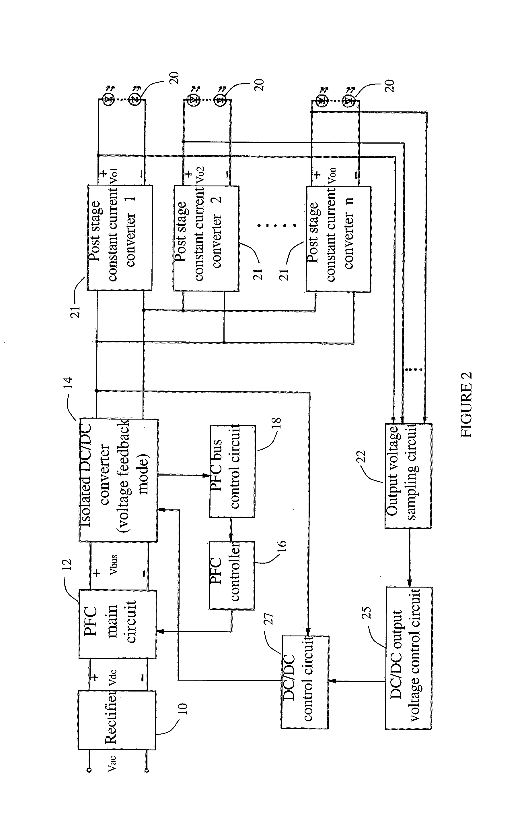
[0017]FIG. 1 discloses a block diagram illustrating an exemplary embodiment of a high efficiency constant current LED driver. The high efficiency constant current LED driver comprises a rectification bridge 10, a PFC main circuit 12, an isolated DC / DC converter 14, a PFC controller 16, and a PFC bus control circuit 18. The rectification bridge 10 rectifies the AC input voltage (Vac) and then outputs the DC voltage (Vdc) to the PFC main circuit 12. The PFC main circuit 12 receives the dc voltage (Vdc) from the rectification bridge 10 and the feedback voltage from the PFC controller 16, and then outputs the DC voltage (Vbus) to the DC / DC converter 14 through a PFC circuit. The isolated DC / DC converter 14 receives the DC voltage (Vbus) from the PFC main circuit 12, and then outputs a DC voltage (Vo) to the LED load 20 through a DC / DC converter and supplies a constant current to the LED load 20. The PFC controller 16 receives the control signal from the PFC bus control circuit 18, and s...


PUM


Abstract

The present invention discloses a high efficiency constant current LED driver, which comprises a rectification bridge, a PFC main circuit, an isolated DC / DC converter, a PFC controller and a PFC bus control circuit. Since the input voltage is an intermediate PFC bus voltage, which varies with the output voltage of the DC / DC converter. When the isolated DC / DC converter is an LLC resonant circuit, the operating frequency of the LLC circuit is close to the resonant frequency within a wide output voltage range. Thus, the gain range and the operating frequency is narrow, and can enable the constant current module to work with a high efficiency at a wide output voltage range. When the isolated DC / DC converter is a symmetric half bridge, or an asymmetric half bridge or a full bridge circuit, the duty cycle of DC / DC circuit is close to 50% within a wide output voltage range. Thus, the changing range of the duty cycle of the DC / DC converter will be narrow and can improve the efficiency dramatically.

Description

CROSS-REFERENCE TO RELATED APPLICATIONS[0001]This application claims priority of Chinese Patent Application No. 200910153404.3 filed Oct. 1, 2009, which is incorporated herein by reference.BACKGROUND OF THE INVENTION[0002]Exemplary embodiments of the present invention generally relate to a high efficiency constant current LED driver. More specifically, it relates to a kind of constant current circuit with active power factor correction (PFC), in which the intermediate bus voltage of power factor correction is adaptively changed with an output voltage, and it can get high efficiency during a wide output range.[0003]A traditional method of a constant current driver for LED application is one active power factor correction (PFC) circuit plus one isolated DC / DC converter, and an output voltage of the PFC circuit is fixed. The topology of an isolated DC / DC converter is generally symmetric half bridge or asymmetric half bridge circuit, full bridge circuit, resonant circuit, which is usual...

Claims


Application Information

Patent Timeline
Patent Type & Authority Applications(United States)
IPC IPC(8): H05B37/02H05B44/00
CPCH05B33/0815Y02B20/348H05B33/0827H05B45/46H05B45/39H05B45/38H05B45/355Y02B20/30H05B45/375H05B45/3725H05B45/382H02M1/007H02M1/4225H02M3/01H02M1/0064H02M3/33571Y02B70/10
Inventor GE, LIANGANYAO, XIAOLIHUA, GUICHAO
Owner INVENTRONICS HANGZHOU
Why Eureka
Try Eureka