Ultrasonic surgical system

a surgical system and ultrasonic technology, applied in the field of ultrasonic surgical systems, can solve the problems of reducing diagnostic capability, inconvenient operation, and excessive heat in the blade, and achieve the effects of reducing diagnostic capability, inconvenient operation, and inconsistency in blade performan

Inactive Publication Date: 2010-05-20
WIENER EITAN T +1
View PDF24 Cites 97 Cited by
  • Summary
  • Abstract
  • Description
  • Claims
  • Application Information

AI Technical Summary

Benefits of technology

[0014]The present invention is directed to eliminating problems in an ultrasonic surgical system that includes an ultrasonic generator that drives a hand piece with an ultrasonic blade or scalpel. These problems include difficulty in locating the mechanical resonance of the blade, excessive heat in the blade, temperature dependance of the components of the ultrasonic generator, inconsistent blade performance, reduced diagnostic capability, limited flexibility in the frequency and amplitude control of the output signal, and susceptibility of the system to interference from an electrosurgical unit. These problems are overcome by utilizing a digital ultrasonic generator system, which is controlled by switches on the generator console, foot activated pedals, and hand activated switches mounted on a hand activation assembly attached to the hand piece.

Problems solved by technology

These problems include difficulty in locating the mechanical resonance of the blade, excessive heat in the blade, temperature dependance of the components of the ultrasonic generator, inconsistent blade performance, reduced diagnostic capability, limited flexibility in the frequency and amplitude control of the output signal, and susceptibility of the system to interference from an electrosurgical unit.

Method used


Image

  • Ultrasonic surgical system
  • Ultrasonic surgical system
  • Ultrasonic surgical system

Examples


Embodiment Construction

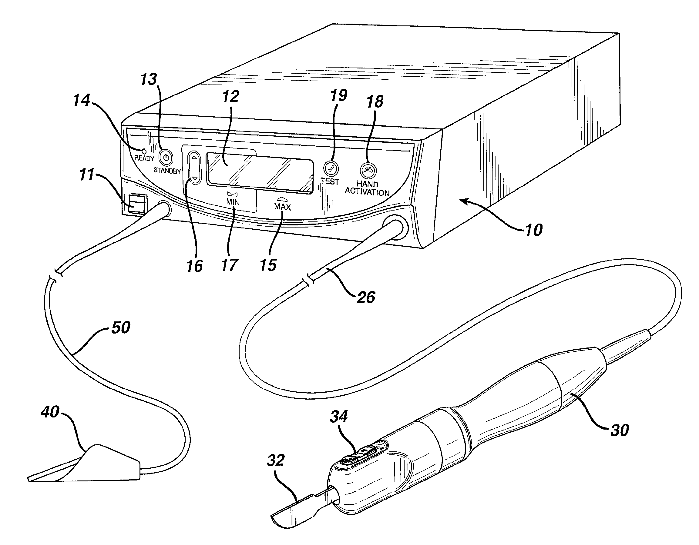
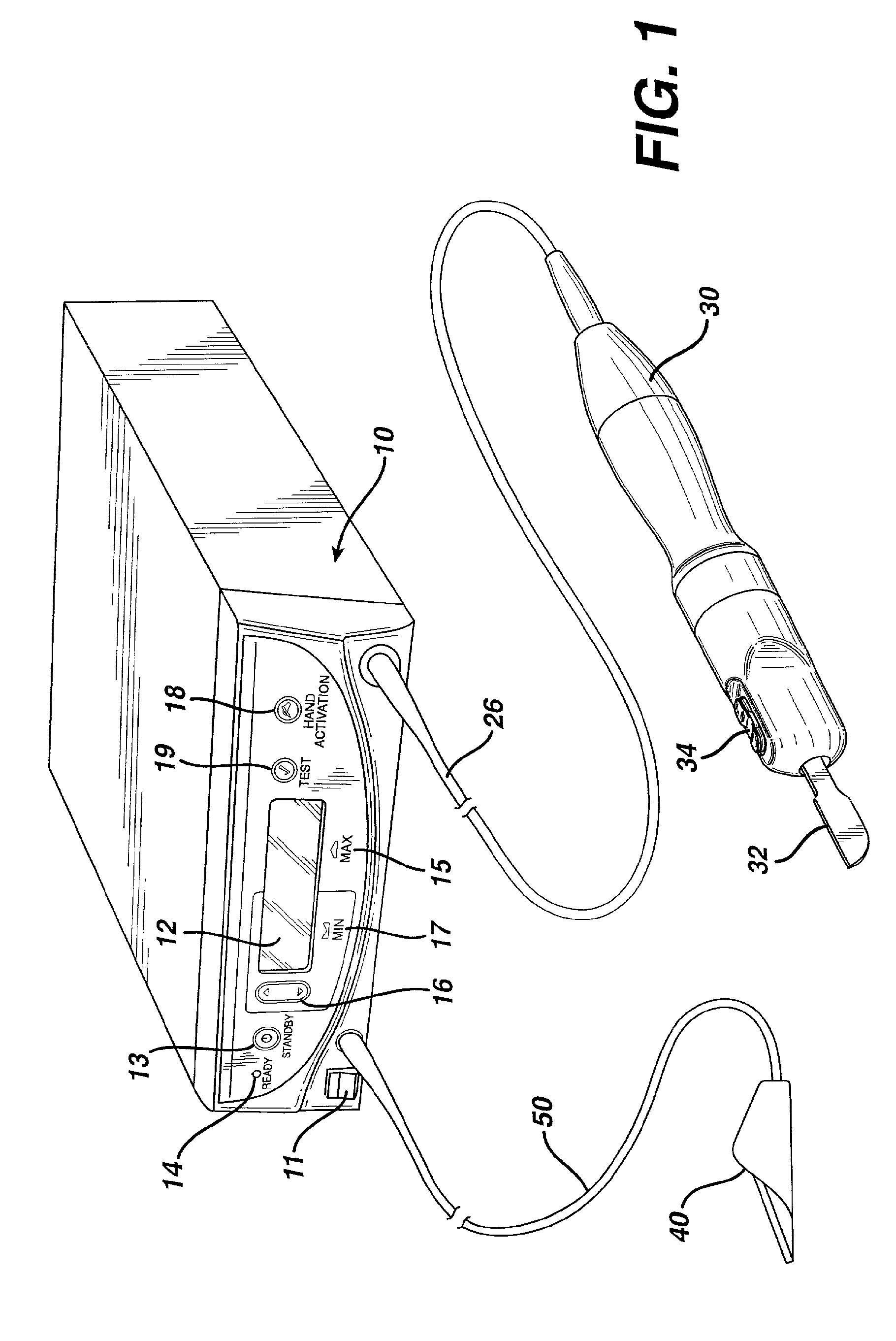
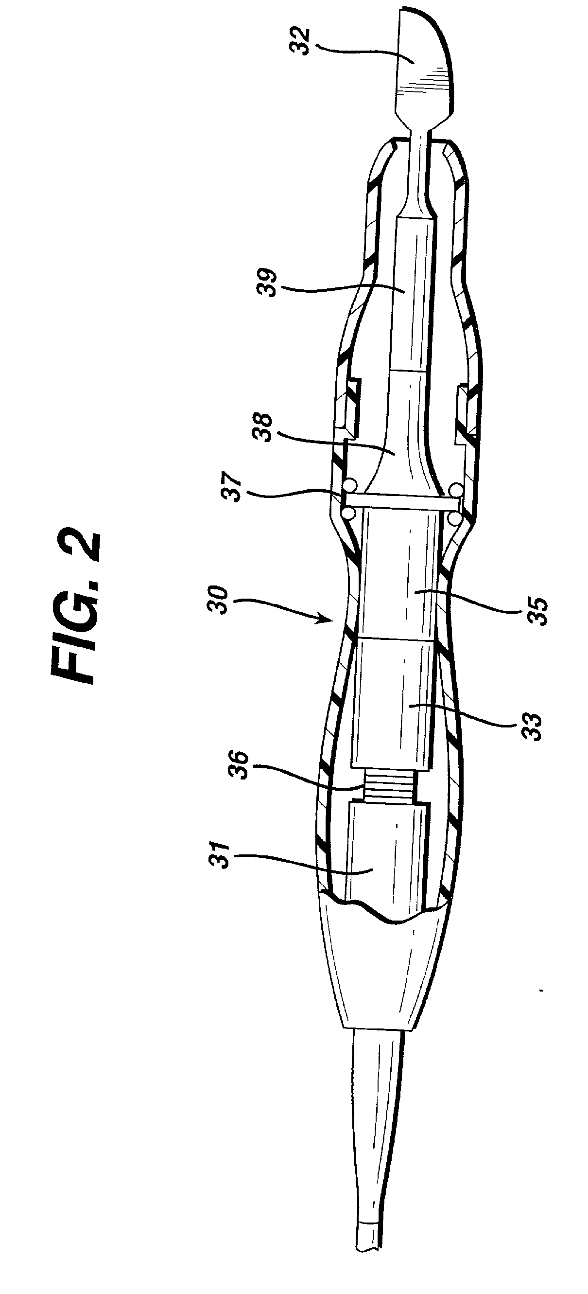
[0035]FIG. 1 shows an illustration of a console or housing 10 for an ultrasonic generator and a control system for the ultrasonic surgical system of the present invention. By means of a first set of wires in cable 20, electrical energy, i.e., drive current, is sent from the console 10 to a hand piece 30 where it imparts ultrasonic longitudinal movement to a surgical device, such as a sharp scalpel blade 32. This blade can be used for simultaneous dissection and cauterization of tissue. The supply of ultrasonic current to the hand piece 30 may be under the control of a switch 34 located on the hand piece, which is connected to the generator in console 10 via a wire in cable 20. The generator may also be controlled by a foot switch 40, which is connected to the console 10 by another cable 50. Thus, in use a surgeon may apply an ultrasonic electrical signal to the hand piece, causing the blade to vibrate longitudinally at an ultrasonic frequency, by operating the switch 34 on the hand ...


PUM


Abstract

An ultrasonic surgical system utilizes a digital control system to generate ultrasonic drive current for transducers that are located in a hand piece and are attached to a surgical scalpel or blade in the hand piece so as to vibrate the blade in response to the current. The digital control includes a digital signal processor (DSP) or microprocessor; a direct digital synthesis (DDS) device; a phase detection logic scheme, a control algorithm for seeking and maintaining resonance frequency; and design scheme that allows to regulate current, voltage, and power delivered to an ultrasonic thereby a device. Such system allows the power versus load output curve to be tailored to a specific hand piece, which improves efficiency and reduces heat. Further, the components of the digital system are much less sensitive to temperature variations, thereby allowing it to operate with narrow as needed frequency range around the desired resonance in order to avoid excitation of other resonances. Also, the digital system provides increased flexibility in locating the resonance frequency of the blade and running diagnostic tests. The start of a user initiated diagnostic test that requires movement of the blade is caused by operating two of the system switches, which guards against accidental operation of the blade which could be harmful if in contact with tissue and also generate false diagnostic results. In addition, the system has interlock with an Electrosurgical unit so that it is not effected by the electromagnetic interference generated by that unit.

Description

BACKGROUND OF THE INVENTION[0001]1. Field of the Invention[0002]This invention relates to ultrasonic surgical systems and, more particularly, to improved apparatus for facilitating the performance of surgical procedures such as simultaneous soft tissue dissection and cauterization of large and small blood vessels through the use of a precisely controlled ultrasonically vibrating blade or scalpel.[0003]2. Description of the Related Art[0004]It is known that electric scalpels and lasers can be used as surgical instruments to perform the dual function of simultaneously effecting the incision and hemostatis of soft tissue by cauterizing tissue and blood vessels. However, such instruments employ very high temperatures to achieve coagulation, causing vaporization and fumes as well as splattering, which increases the risk of spreading infectious diseases to operating room personnel. Additionally, the use of such instruments often results in relatively wide zones of thermal tissue damage.[0...

Claims


Application Information

Patent Timeline
Patent Type & Authority Applications(United States)
IPC IPC(8): A61B17/32
CPCA61B2017/00017A61B17/320068A61B2017/320089A61B2017/320082
Inventor WIENER, EITAN T.DONOFRIO, WILLIAM T.
Owner WIENER EITAN T
Why Eureka
Try Eureka