Cable bundling device

a cable and cable technology, applied in the field of cable bundling, can solve the problems of inability to effectively improve the performance and throughput of production, degrade the quality of the final product of the ribbon cable, and the inability to achieve the effect of improving the efficiency and throughput of conventional methods, enhancing the aesthetics of the bundling, and simplifying the structur

Inactive Publication Date: 2012-07-17
ADVANCED FLEXIBLE CIRCUITS
View PDF19 Cites 9 Cited by
  • Summary
  • Abstract
  • Description
  • Claims
  • Application Information

AI Technical Summary

Benefits of technology

[0007]Thus, an objective of the present invention is to provide a cable bundling device that overcomes the drawbacks occurring in the known, manually-operated cable bundling machines.
[0012]With the solution provided by the present invention, bundling speed and location can be adjusted and properly controlled in the bundling operation in an automatic manner, whereby advantages of high-speed and regular and ordered bundling with consistent quality can be realized in wrapping a bundling material around a cluster section, or a selected portion thereof, of a flexible circuit board based ribbon cable to form a bundled structure. The drawback of poor performance occurring in the conventional human based operation, which leads to inconsistency of performance of production and makes it impossible to improve the efficiency and throughput of the conventional ways, can be eliminated.
[0013]Further, the cable collection mechanism adopted in the present invention functions to manage a cable to be processed before the bundling material is wrapped around the cable, and this helps preventing the cable, or portions of the cable, from distributed in a random and disordered manner and also enhances aesthetics of the bundling.
[0014]Further, as compared to the conventional machines, the cable bundling device according to the present invention offers a simplified structure and can be automatized to reduce the manufacturing costs, making it economic effective and improving market competition power.

Problems solved by technology

Manual operation of setting a bundling structure on the cluster section, or a selected portion thereof, of a flexible circuit board based ribbon cable to form a bundled structure often leads to inconsistent quality of the final products of ribbon cables.
Further, manual operation may also causes degraded performance of production due to human factors and consequently, the performance of production is inconsistent, making it impossible to effectively improve the performance and throughput of production.
Further, a known machine that is used to bundle a flexible circuit board based ribbon cable is of a complicated structure that is composed of a great number of components / parts and is only applicable to ribbon cables of a fixed length, meaning the length of ribbon cables to be processed by the machine must be fixed and is not allowed to vary, so that the machine has only a very limited range of application.
Further, the operation of such a known machine is quite time- and labor-consuming and is difficult.
In addition, the bundling operation carried out with such a known machine often leads to irregularity and disorder of the bundled cable, so that the performance and effectiveness of the cable are affected.
Further, the operation of such a known machine cannot be automatized, and is operated in such a low speed, non-adjustable, and hard to control manner.
Consequently, the manufacturing expense is raised, making it not economically effective and showing low market competition power.
Such drawbacks of the known machine have troubled the industry for quite a long time and a solution to effectively improve the operation performance of a machine of this kind and enhance the value of the product thereof is desired in this industry.

Method used


Image

  • Cable bundling device
  • Cable bundling device
  • Cable bundling device

Examples


Embodiment Construction

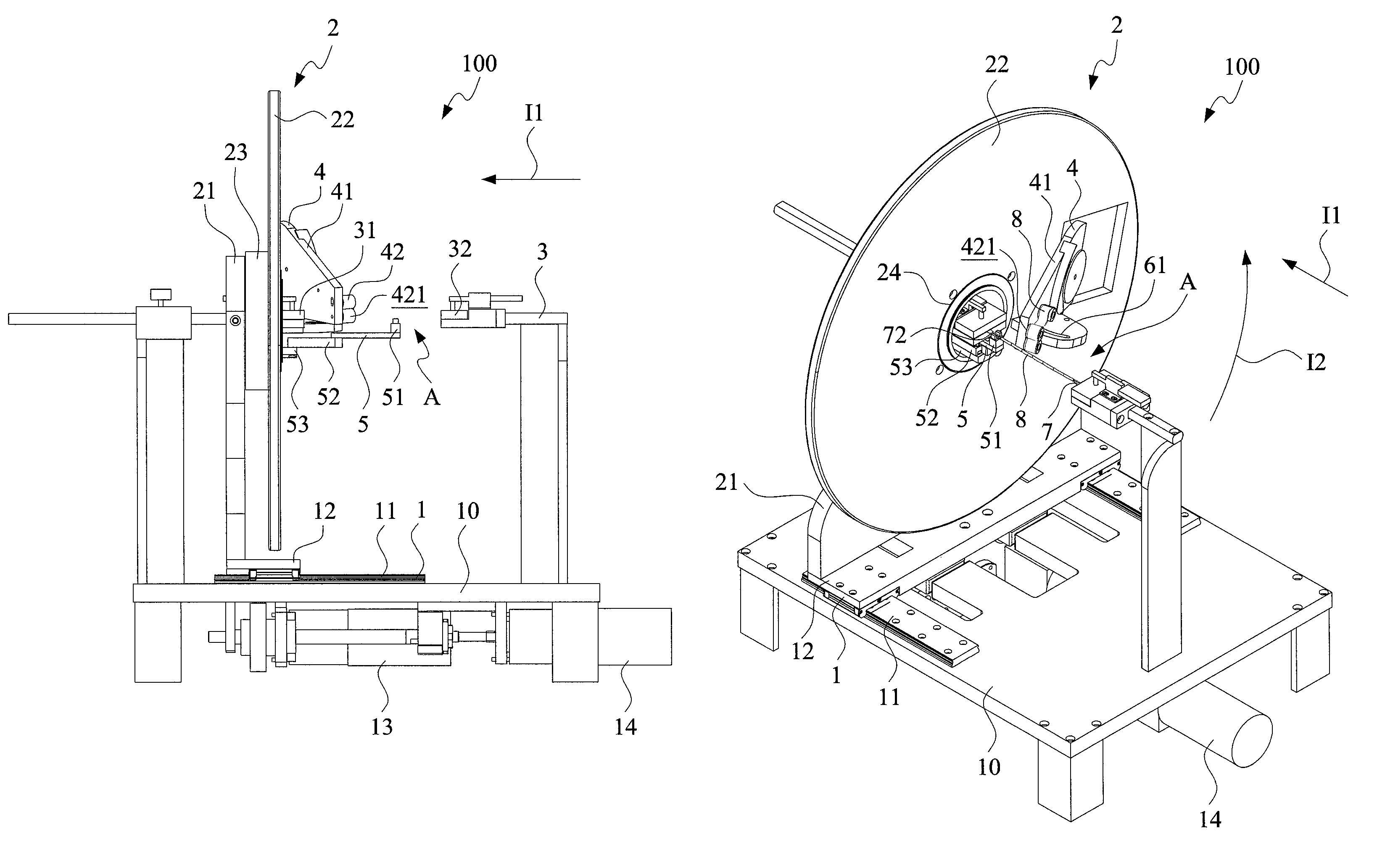
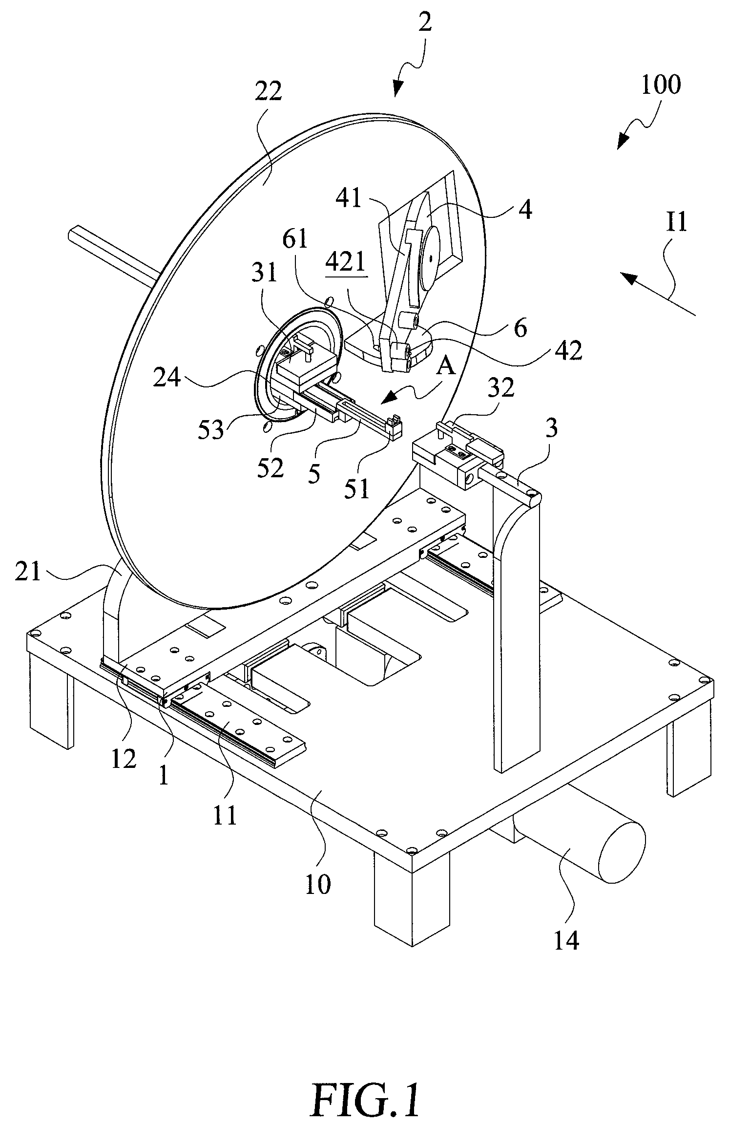
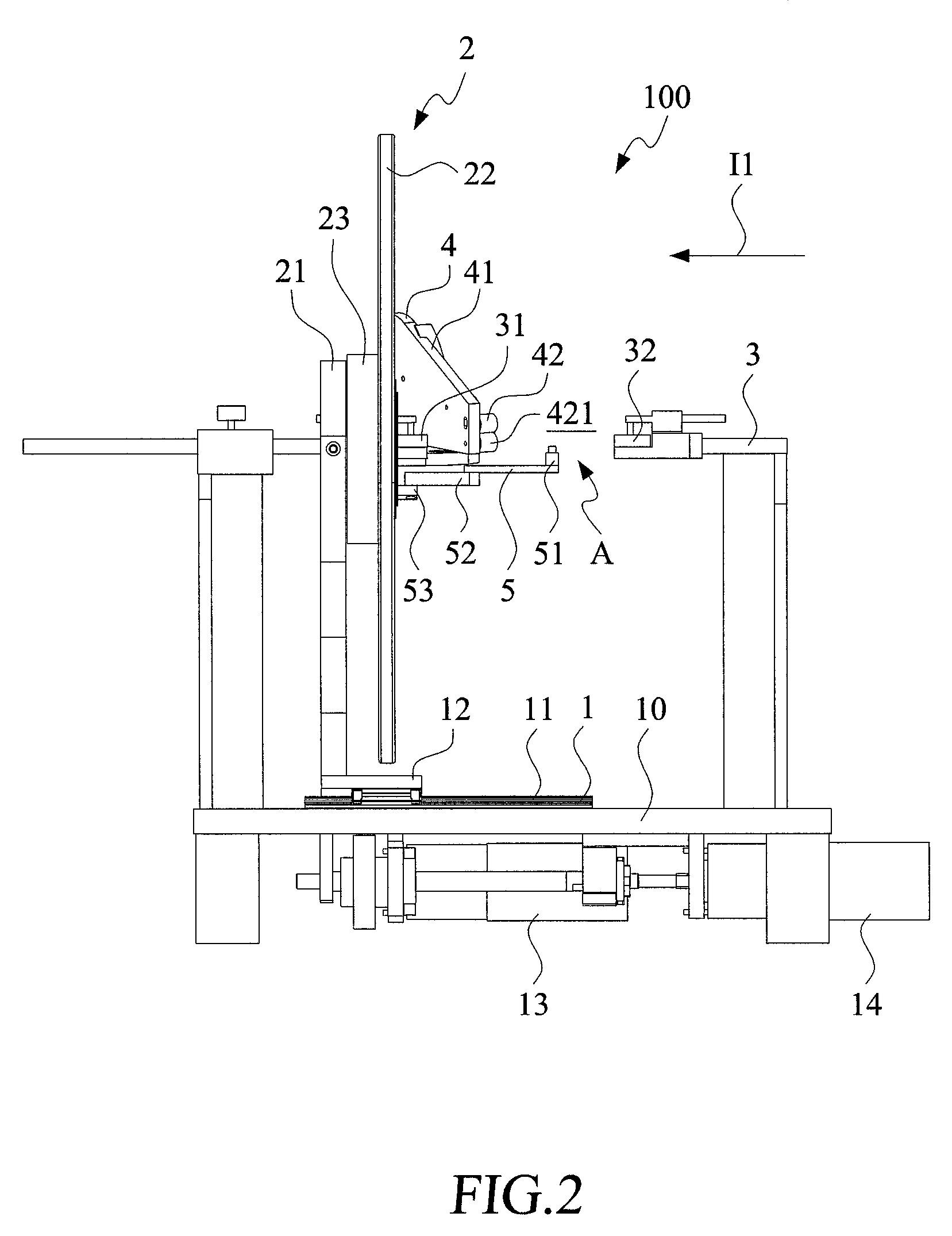
[0027]With reference to the drawings and in particular to FIGS. 1 and 2, a cable bundling device constructed in accordance with a first embodiment of the present invention, generally designated at 100, comprises a track assembly 1, a rotation mechanism 2, a cable positioning mechanism 3, and a wrapping mechanism 4. The track assembly 1 comprises a track 11 mounted on a chassis 10 and a slide 12, which is slidably mounted to the track 11. The slide 12 is coupled to a drive unit 13, and the slide 12 can be driven by the drive unit 13 to slide on the track 11 in an axial movement direction 11.

[0028]The rotation mechanism 2 comprises a support base 21 and a rotary unit 22. The support base 21 is mounted to the slide 12 of the track assembly 1. The rotary unit 22 is coupled to a predetermined position on the support base 21 through a transmission assembly 23. In the instant embodiment, the rotary unit 22 comprises a rotatable wheel. The transmission assembly 23 is driven by a drive unit ...


PUM

PropertyMeasurementUnit
diameteraaaaaaaaaa
electrically conductiveaaaaaaaaaa
flexibleaaaaaaaaaa

Abstract

A cable bundling device includes a cable positioning and a wrapping mechanism. The cable positioning mechanism includes a first clamping member and a second clamping member, which are set in a working zone. The first and second clamping members function to respectively clamp ends of a cable. One of the wrapping mechanism and the cable positioning mechanism is selectively rotatable to have the bundling material loaded in the wrapping mechanism wrapped around the cable.

Description

FIELD OF THE INVENTION[0001]The present invention relates to the design of a bundling device, and in particular to cable bundling device that bundles a cable by wrapping a bundling material around the cable.BACKGROUND OF THE INVENTION[0002]Recently, flexible circuit board technology has found applications in ribbon cables. The flexible circuit board based ribbon cable products that are commonly available in the market are often of a circuit board structure comprising a single-sided board, a double-sided board, or a multi-layer board, depending on the number of transmission lines required.[0003]In certain currently prevailing consumer electronic devices, such as notebook computers, liquid crystal displays, digital cameras, mobile phones, and touch panels, and a number of other consumer electronic products, a cover or a display screen is often coupled to a device body of the electronic device with a hinge structure. To transmit electrical signals from the body of the electronic device...

Claims


Application Information

Patent Timeline
Patent Type & Authority Patents(United States)
IPC IPC(8): B65B13/10B65B13/12B65B11/02B65B27/10B65B11/04
CPCB65B27/06B65B63/06
Inventor SU, KUO-FULIN, GWUN-JINCHUO, CHIH-HENG
Owner ADVANCED FLEXIBLE CIRCUITS
Why Eureka
Try Eureka