Doubly-controlled asynchronous generator

a technology of asynchronous generators and generators, which is applied in the direction of motors, dynamo-electric machines, engine control parameters, etc., can solve the problems of disturbance of the grid flow directly to the stator, system significant cost, and disturbance of the power production of such generators, so as to increase the voltage capability of the converter, the effect of widening the slip rang

Inactive Publication Date: 2008-06-26
WIND TO POWER SYST
View PDF6 Cites 100 Cited by
  • Summary
  • Abstract
  • Description
  • Claims
  • Application Information

AI Technical Summary

Benefits of technology

[0009]The present invention resolves or reduces one or more of the above disadvantages by providing a generator in which the stator voltage can be set independently of the grid. This avoids the problems associated with variable grid voltage. It also allows the stator voltage to be set lower, which permits a larger slip range without increasing the voltage capability of the converters. The system also provides a motor that provides the same advantages.

Problems solved by technology

However, this system has significant cost because the power converter has to handle the entire power of the generator and, therefore, must be very robust.
However, the doubly-fed asynchronous generator system described in the '187 patent has some disadvantages, resulting from the direct connection of the generator's stator to the three-phase electric power distribution grid.
These disadvantages include the fact that disturbances in the grid flow directly to the stator.
Thus, significant voltage variations in the grid, such as those due to electrical loads being connected or disconnected, balanced as well as unbalanced short circuits, or similar contingencies, disturb the power production of such generators.
Furthermore, when the doubly-fed asynchronous generators of the prior art are connected to a wind turbine, the system thus formed cannot be connected to the electric power distribution grid when wind speed is low.
Since part of the appeal of these systems is that they are able to use relatively low-cost inverters with a relatively small voltage capability, the required low rotational speed of the wind turbine cannot be reached because of the limited voltage ceiling of the rotor side inverter.

Method used


Image

  • Doubly-controlled asynchronous generator
  • Doubly-controlled asynchronous generator
  • Doubly-controlled asynchronous generator

Examples


Embodiment Construction

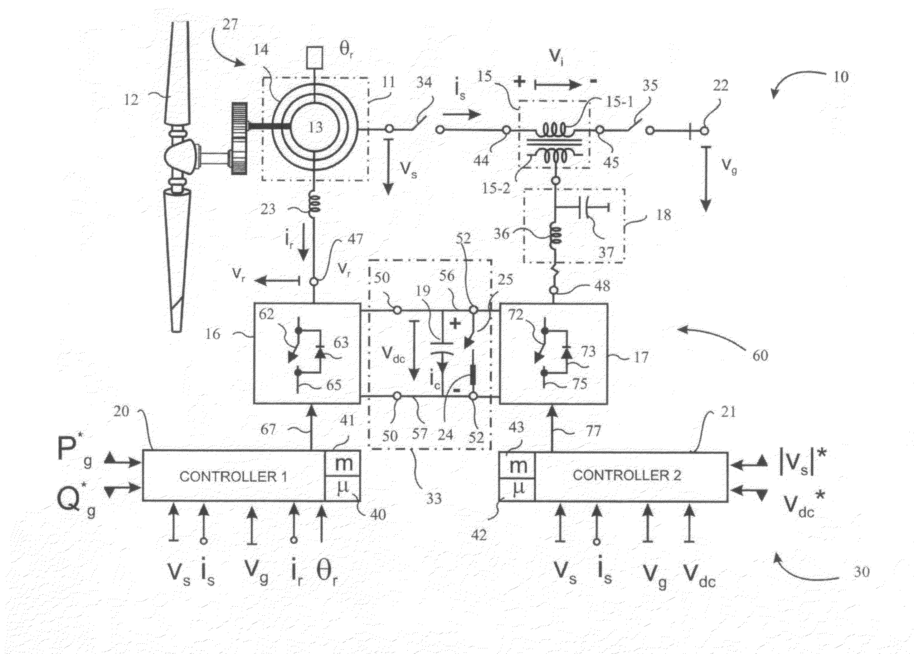
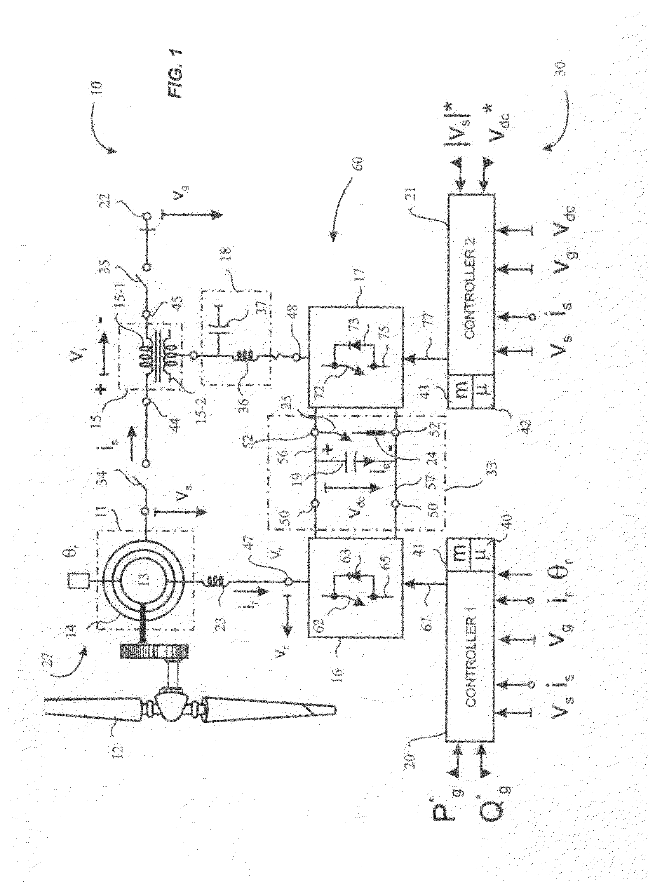
[0031]FIG. 1 is a block diagram illustrating a preferred embodiment of a generator or motor system 27 according to the invention. In this embodiment, the generator system 27 is incorporated into a wind turbine generator 10, which includes a turbine 12 and generator system 27. Generator system 27 includes a generator 11, often referred to as an induction generator, and a controller 30. Generator 11 includes a rotor 13 and a stator 14. System 10 preferably is a variable speed wind turbine system, and generator 11 preferably is a doubly-fed asynchronous generator 11. Turbine 12 is connectable to generator 11 in such a way that the turbine is coupled to the rotor 13 that turns inside stator 14 of the generator 11. Power produced by system 10 is fed to a power grid 22. As will be seen in detail below, the generator system 27 according to the invention controls the voltage Vs applied to the stator by injecting a voltage Vi into the stator / grid connection via transformer 15 using a novel c...


PUM


Abstract

An electric power generator system or a motor comprising a doubly-fed asynchronous generator or motor comprising a stator and a rotor, a transformer having a first winding and a second winding, the first winding having a first end and a second end; and wherein the stator and the transformer are connectable in series with an electric power distribution grid.

Description

CROSS-REFERENCE TO RELATED APPLICATIONS[0001]This application claims priority to the application filed in Spain under PCT Application No. PCT / ES2006 / 070199 on Dec. 22, 2006 designating the United States.FIELD OF THE INVENTION[0002]The present invention refers, in general, to a doubly-fed asynchronous generator, or induction generator, connectable to a turbine such as a wind turbine, to generate electric power that is delivered to an electric power distribution grid. The system also applies to a motor.BACKGROUND OF THE INVENTION[0003]Currently, generators connected to variable speed wind turbines are used in the production of electric power that reaches the end users through the three-phase electric power distribution grid. Such generators have been known for nearly a hundred years. See, for example, U.S. Pat. No. 5,083,039 issued Jan. 21, 1992 to Richardson et al. (hereinafter “the '039 patent”), which describes a system in which the generator stator is connected to the grid via an ...

Claims


Application Information

Patent Timeline
Patent Type & Authority Applications(United States)
IPC IPC(8): H02P9/04F03D9/00
CPCH02J3/1807H02J3/1878H02P2101/15Y02E10/725Y02E40/30H02P9/007F03D7/0272F03D7/0276F05B2220/70646F05B2270/32Y02E10/72Y02E10/76
Inventor CORCELLES PEREIRA, JOSE MANUELRODRIGUEZ-AMENEDO, JOSE LUISARNALTES-GOMEZ, SANTIAGO
Owner WIND TO POWER SYST
Why Eureka
Try Eureka