Screw for use in nonmetal objects

a non-metal object and screw technology, applied in the direction of screws, threaded fasteners, fastening means, etc., can solve problems affecting screwing efficiency, and achieve the effects of reducing screwing resistance, enhancing cutting capability, and increasing screwing speed

Inactive Publication Date: 2010-04-27
ZYH YIN ENTERPRISE
View PDF11 Cites 8 Cited by
  • Summary
  • Abstract
  • Description
  • Claims
  • Application Information

AI Technical Summary

Benefits of technology

[0006]Therefore, the objects of the present invention are to provide a screw which is conducive to enhance cutting capability, reduce the screwing resistance for a higher screwing speed and prevent the destruction of the object.
[0007]The screw relating to the present invention comprises a screw head, a shank, a drilling portion and a plurality of threads; wherein a plurality of cut-aiding portions are located between any of two threads, and each of which consists of a longer cutting surface and a shorter cutting surface positioned toward opposite directions. A cutting edge formed by two adjacent cutting surfaces in any of the two adjacent cut-aiding portions presents in a fastening direction. Further, a ridge defined by the raked faces with different slopes on the longer cutting surface also extends to the shorter cutting surface. According to the aforementioned configurations, the cutting edge assists the threads to thoroughly sever and shatter the fibers and the debris, which can be received into the cut-aiding portions with larger spaces, and further accompanying with the assistance of the ridge to cut and smoothly guide the debris out, thereby decreasing the screwing resistance and improving the problem of the destruction to the object.

Problems solved by technology

In this manner, the aforementioned debris and the fibers facilely make a larger screwing resistance and further cause the burden of the operators and the destruction of the object 2 while rotating the screw 1, thus affecting the screwing efficiency.

Method used


Image

  • Screw for use in nonmetal objects
  • Screw for use in nonmetal objects
  • Screw for use in nonmetal objects

Examples


Embodiment Construction

[0018]Before the present invention is described in greater detail, it should be noted that the like elements are denoted by the same reference numerals throughout the disclosure.

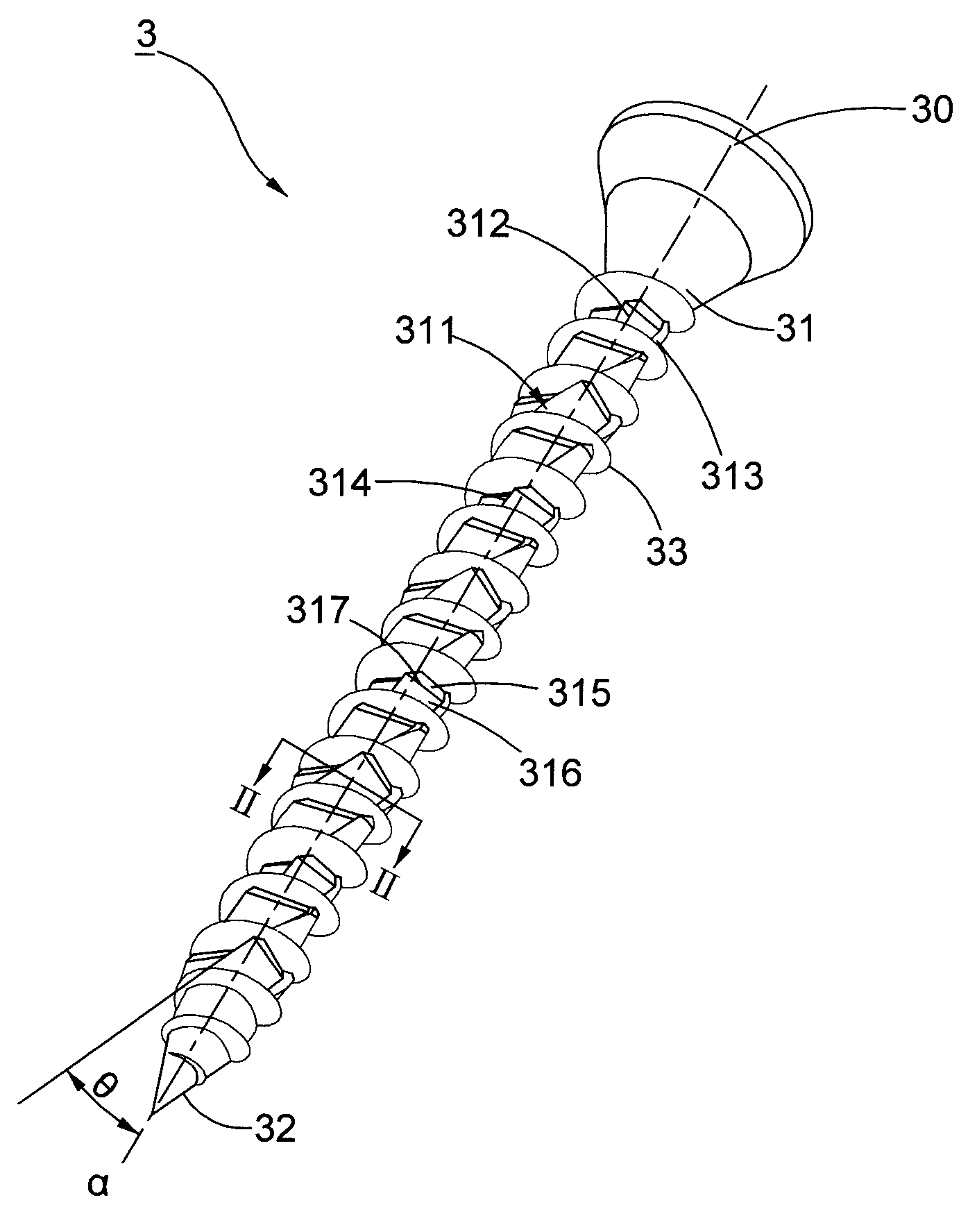
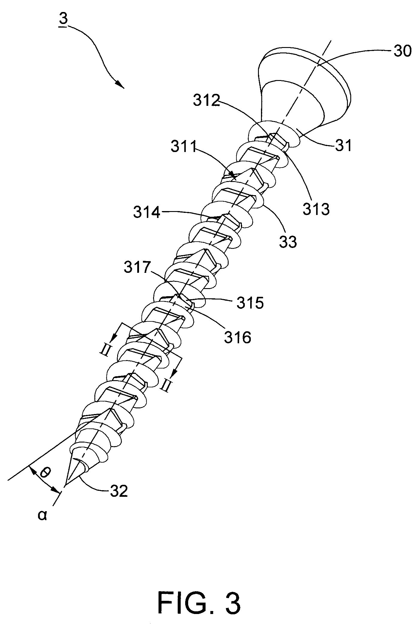
[0019]Referring to FIG. 3, a screw 3 of a first preferred embodiment comprises a screw head 30, a shank 31 longitudinally extending from the screw head 30 along a shank axis PP P, a drilling portion 32 disposed on the distal end of the shank 31, opposite to the screw head 30, and a plurality of threads 33 disposed on the shank 31; wherein a plurality of cut-aiding portions 311 disposed on the shank 31 and located between any of the two threads 33. The cut-aiding portions 311 are adjacent to each other. Each of the cut-aiding portions 311 consists of a longer cutting surface 312 and a shorter cutting surface 313 joined thereto, which are positioned toward opposite directions. The shorter cutting surface 313 can be parallel to (shown in FIG. 4) or inclined to (shown in FIG. 3) the shank axis P, and it is adopt...


PUM

PropertyMeasurementUnit
angleaaaaaaaaaa
cutting surfaceaaaaaaaaaa
angleaaaaaaaaaa

Abstract

The present invention pertains to a screw for use in nonmetal objects comprising a plurality of cut-aiding portions formed by the longer and shorter cutting surfaces inclined toward opposite directions. Further, a cutting edge formed by the junction of any two adjacent cutting surfaces presents in a fastening direction of the screw. Thus, the cutting edge assists the threads to thoroughly severe and to shatter the fibers and debris of the objects, which can also be accommodated into the cut-aiding portions. Also, the ridge of the longer cutting surface aids in cutting fibers and further guides the debris out. In this manner, the present invention facilitates to enhance cutting capability for obtaining less screwing resistance, to prevent the destruction of the object and to increase the screwing speed.

Description

BACKGROUND OF THE INVENTION[0001]1. Field of the Invention[0002]The present invention relates to a screw, in particular a screw for use in nonmetal objects.[0003]2. Description of the Related Art[0004]Referring to FIG. 1, a conventional screw 1 comprises a screw head 10, a shank 11 extending from the head 10, a drilling portion 12 disposed at the distal end of the shank 11, and a plurality of threads 13 disposed on the shank 11; wherein a plurality of slots 14 are disposed on the surface of the shank 11, which results of the slight concavities in cross section PP P of FIG. 1 separately presented around the periphery of the shank 11, as shown in FIG. 2. In operation, the screw 1 is rotated into the wood object 2 by exerting the slots 14 to cut the fibers and accommodate the debris.[0005]Generally, in regard to the resilience of the wood fibers and the expeditious rotation, the fibers would not be thoroughly received into the slots 14 with smaller spaces, thus rendering part of fibers...

Claims


Application Information

Patent Timeline
Patent Type & Authority Patents(United States)
IPC IPC(8): F16B25/00
CPCF16B25/0015F16B25/0052F16B25/103F16B25/0078F16B25/0068
Inventor CHEN, CHI-HSIANG
Owner ZYH YIN ENTERPRISE
Why Eureka
Try Eureka