Light shielding member, a line head and an image forming apparatus using the line head

a line head and light shielding technology, applied in printing and other directions, can solve the problems of reducing the quality of the image obtained by the image forming apparatus, and achieve the effects of less ghosting, less stray light, and reduced ghosting

Inactive Publication Date: 2010-04-27
SEIKO EPSON CORP
View PDF8 Cites 5 Cited by
  • Summary
  • Abstract
  • Description
  • Claims
  • Application Information

AI Technical Summary

Benefits of technology

[0007]An advantage of some aspects of the invention is to provide a light shielding member producing less stray light, a line head with a reduced occurrence of ghost using the light shielding member and an image forming apparatus with a smaller reduction in image quality using the line head.

Problems solved by technology

The remaining light becomes the cause of crosstalk and stray light.
A latent image formed on the photosensitive member becomes unclear by the ghost, whereby the quality of an image obtained by the image forming apparatus also decreases.

Method used


Image

  • Light shielding member, a line head and an image forming apparatus using the line head
  • Light shielding member, a line head and an image forming apparatus using the line head
  • Light shielding member, a line head and an image forming apparatus using the line head

Examples


first embodiment

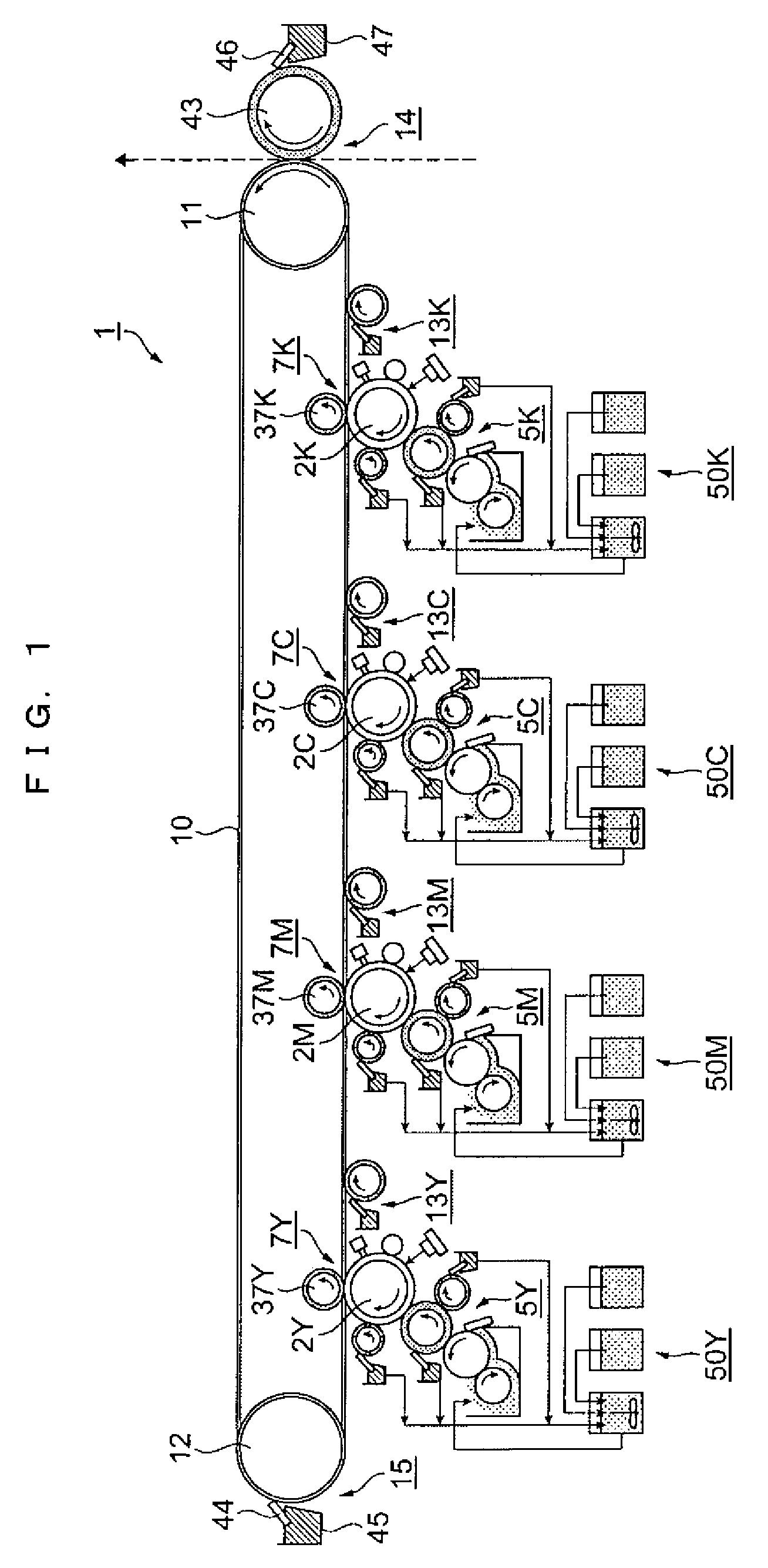
[0029]FIG. 1 is a diagram schematically and partly showing an image forming apparatus 1 according to this embodiment. An image forming apparatus 1 is an apparatus for forming an image using a liquid developer, in which toner particles are dispersed in a liquid carrier. It should be noted that rotating directions are shown by solid-line arrows in rotational members. In FIG. 1, the image forming apparatus 1 includes an endless intermediate transfer belt 10 as an intermediate transfer medium, a drive roller 11 and a driven roller 12 on which the intermediate transfer belt 10 is mounted, a secondary transfer device 14, an intermediate transfer belt cleaning device 15 and primary transfer units. The primary transfer units include primary transfer units 50Y, 50M, 50C and 50K corresponding to the respective colors of yellow (Y), magenta (M), cyan (C) and black (K). In the following description, Y, M, C and K indicating the respective colors are affixed to the reference numerals of devices,...

second embodiment

[0098]An image forming apparatus and a line head according to this embodiment differ from those of the first embodiment in the construction of the light shielding member, but the other constructions thereof are the same as in the first embodiment. FIG. 11 is a partial enlarged sectional view showing the vicinity of a glass substrate 450, a light shielding member 490 and a microlens array 430 according to the second embodiment of the invention. In FIG. 11, the light shielding member 490 of this embodiment is constructed such that thickness d1 of a space layer 443 between a light shielding plate 445 and a light shielding plate 442, thicknesses d2, d3, d4 of space layers 443 between the light shielding plates 442 and thickness d5 of a space layer 447 between the light shielding plate 442 and the glass substrate 450 differ. The light shielding plates 442, 445 are arranged such that the relationship of d1, d2, d3, d4 and d5 is d12345. The other construction of the light shielding member ...

third embodiment

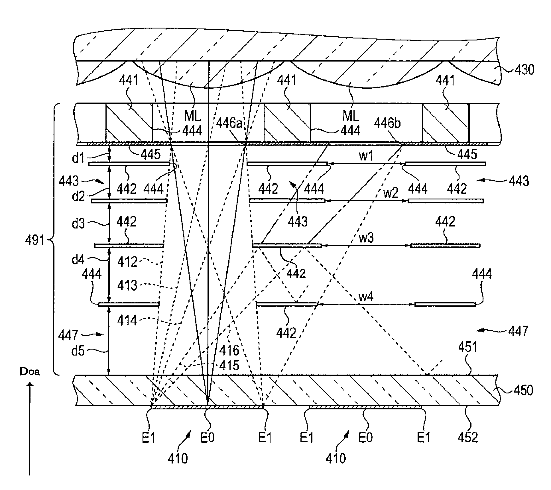
[0101]An image forming apparatus and a line head according to this embodiment differ from those of the second embodiment in the construction of the light shielding member, but the other constructions thereof are the same as in the second embodiment. FIG. 12 is a partial enlarged sectional view showing the vicinity of a glass substrate 450, a light shielding member 491 and a microlens array 430 according to the third embodiment of the invention. In FIG. 12, the light shielding member 491 of this embodiment is constructed such that the sizes of the light guide holes 44 differ depending on light shielding plates 442. Specifically, when w1 denotes the width of the light guide holes 444 of the light shielding plate 442 closest to the microlens array 430 and w2, w3, w4 denote the widths of the light guide holes 444 of the light shielding plates 442 in the order toward the glass substrate 450, the widths of the respective light guide holes are: w1234. A spacing d1 between a light shielding...


PUM


Abstract

A line head, includes: a head substrate that includes a plurality of light emitting element groups as groups of light emitting elements; a lens array that includes a plurality of lenses each of which faces the corresponding light emitting element group in a first direction; and a light shielding member that is disposed between the head substrate and the lens array and includes a plurality of light shielding plates which are arranged side by side in the first direction while defining a space layer therebetween, wherein each of the plurality of light shielding plates is provided with a plurality of light guide holes penetrating in the first direction and facing the plurality of light emitting element groups in the first direction respectively, the plurality of light guide holes facing each of the light emitting element groups are arranged in the first direction respectively to form a plurality of light guide portions, and lights from the plurality of light emitting element groups are incident on the plurality of lenses through the plurality of light guide portions respectively.

Description

CROSS REFERENCE TO RELATED ART[0001]The disclosure of Japanese Patent Applications No. 2007-127653 filed on May 14, 2007 and No. 2008-67398 filed on Mar. 17, 2008 including specification, drawings and claims is incorporated herein by reference in its entirety.BACKGROUND[0002]1. Technical Field[0003]The invention relates to a light shielding member used in a line head, a line head for scanning a surface of a latent image carrier to be scanned with light, and an image forming apparatus.[0004]2. Related Art[0005]A line head for forming a latent image by scanning a surface-to-be-scanned of a photosensitive member as a latent image carrier with light is used as a light source of an electrophotographic printer as an image forming apparatus. As, for example, disclosed in JP-A-6-270468, an optical printer head as a line head is proposed to use light emitting element groups (“LED arrays” in JP-A-6-270468) formed by arraying a plurality of light emitting diode devices (hereinafter, LEDs) as l...

Claims


Application Information

Patent Timeline
Patent Type & Authority Patents(United States)
IPC IPC(8): B41J2/45
CPCB41J2/465B41J2/451
Inventor TSUJINO, KIYOSHINOMURA, YUJIRO
Owner SEIKO EPSON CORP
Why Eureka
Try Eureka