Beam divergence and various collimators for holographic or stereoscopic displays

Active Publication Date: 2016-07-19
SEEREAL TECHNOLOGIES
View PDF32 Cites 11 Cited by
  • Summary
  • Abstract
  • Description
  • Claims
  • Application Information

AI Technical Summary

Benefits of technology

The patent describes a lighting system that uses a special diffraction grating to efficiently distribute and control the light from a small number of light sources. This allows for better utilization of the available light power and reduces the need for multiple light sources. The system also includes a volume hologram to limit the angular range of light waves and a space division multiplexing option to deflect light without the need for a light-absorbing shutter. Additionally, the patent describes a method to illuminate the entrance surface of an enlarging unit using a volume grating and cascading light waveguides or switches. The patent also includes a technical solution to avoid interference between the volume grating and the reflective light modulator. Overall, this patent provides a technical solution for efficient and controlled lighting using special diffraction gratings.

Problems solved by technology

There are two major problems one faces when realising holographic displays with large screen size:If a large-area light modulator, e.g. having a diagonal measurement of 24″, is used to encode the hologram, then this large area of the light modulator must be illuminated uniformly with sufficiently coherent light.In contrast, if a small light modulator is combined with a projection arrangement, then the device will be deeper than 1 m if it has the same screen size of 24″ and if conventional optical means such as lenses and mirrors are used.
The second problem can only be solved if other means than conventional optical means are used to enlarge the illumination device and / or the light modulator.
However, this goes along with the disadvantage that the optical arrangement is rather voluminous and particularly long in the axial direction, so that it can hardly be used as a holographic desktop display because of its large depth.
However, the arrangement is still too voluminous to be used as a holographic desktop display.

Method used


Image

  • Beam divergence and various collimators for holographic or stereoscopic displays
  • Beam divergence and various collimators for holographic or stereoscopic displays
  • Beam divergence and various collimators for holographic or stereoscopic displays

Examples


Embodiment Construction

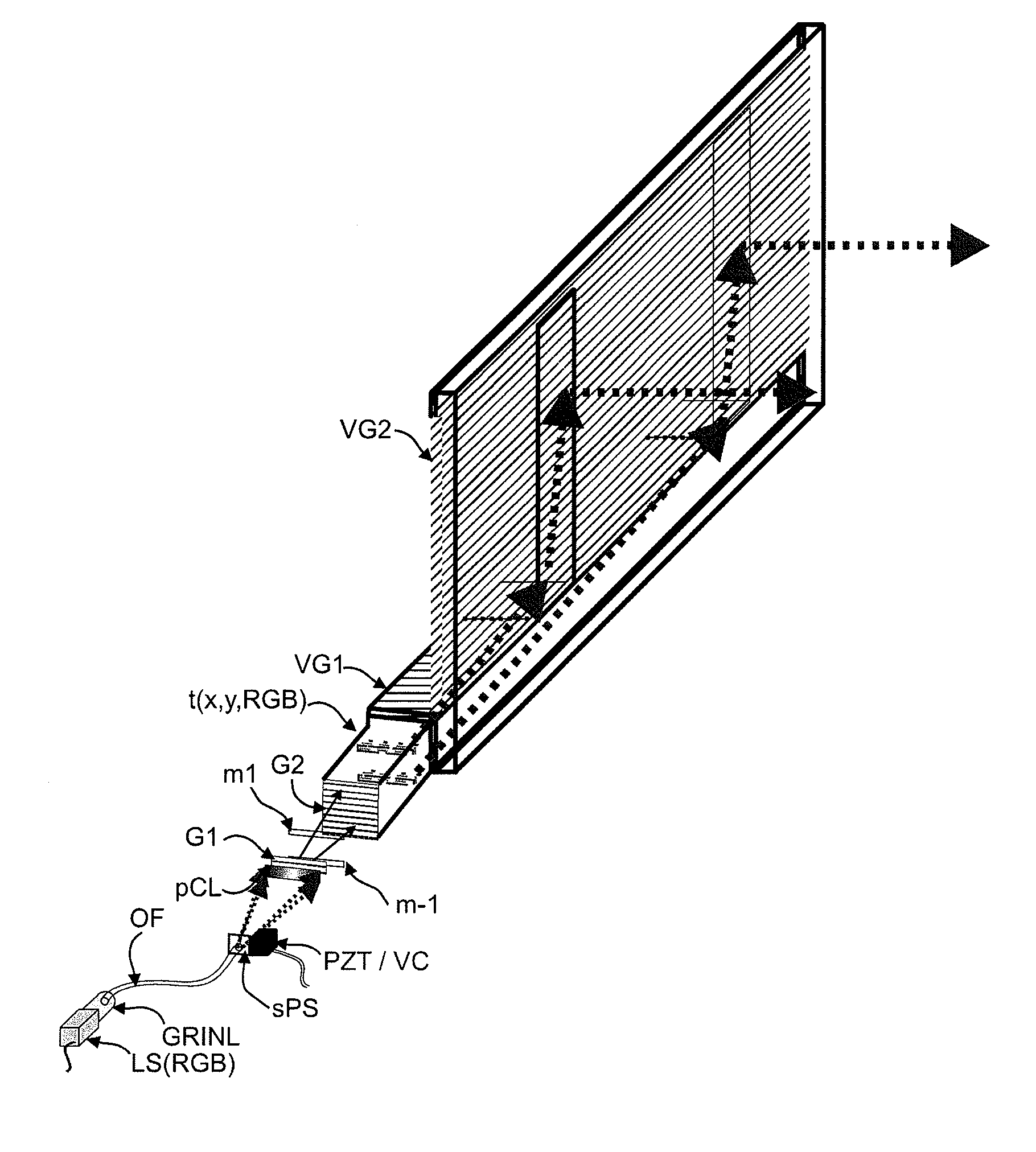
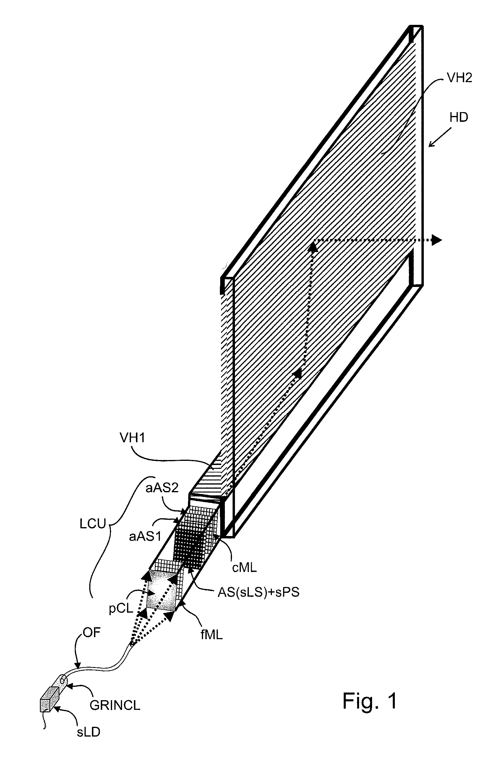
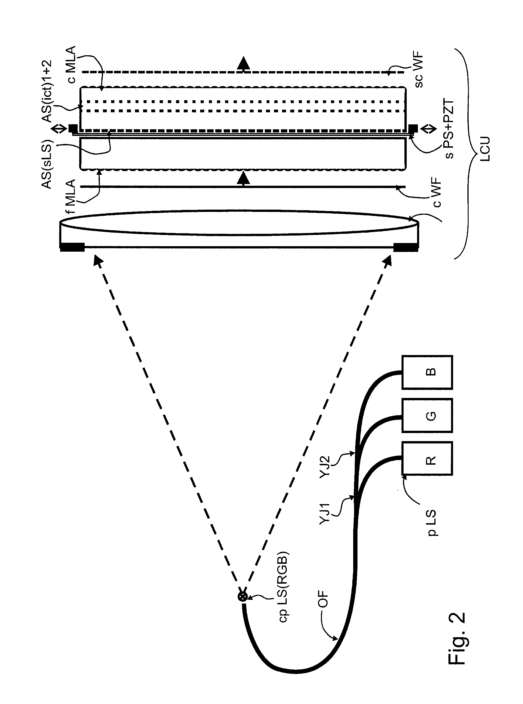
[0091]FIG. 1 shows an embodiment of an illumination device of the holographic display, said illumination device comprising a light collimation unit in front of two transmissive volume gratings which broaden the light wave field in two different directions one after another. Here, the light collimation unit which comprises two micro-lens arrays preferably has a small size.

[0092]The light wave field is broadened anamorphically, i.e. the enlargement factor differs in the two different directions.

[0093]The light which is emitted by a power-(P)-and-wavelength-(λ)-stabilised laser diode sLD is coupled into an optical fibre OF through a gradient-index lens GRINCL.

[0094]The divergent light which is emitted by the end of the optical fibre is collimated by the light collimation unit, i.e. formed into a plane wave, which means that the rays of light are oriented in parallel through this collimation. The light collimation unit comprises a primary collimation lens pCL.

[0095]The first micro-lens ...


PUM

PropertyMeasurementUnit
Angleaaaaaaaaaa
Angleaaaaaaaaaa
Angleaaaaaaaaaa

Abstract

A holographic display with an illumination device, an enlarging unit and a light modulator. The illumination device includes at least one light source and a light collimation unit, the light collimation unit collimates the light of the at least one light source and generates a light wave field of the light that is emitted by the light source with a specifiable angular spectrum of plane waves, the enlarging unit is disposed downstream of the light collimation unit, seen in the direction of light propagation, where the enlarging unit comprises includes a transmissive volume hologram realizing an anamorphic broadening of the light wave field due to a transmissive interaction of the light wave field with the volume hologram, and the light modulator is disposed upstream or downstream of the anamorphic enlarging unit, seen in the direction of light propagation.

Description

CROSS REFERENCE TO RELATED APPLICATIONS[0001]This application claims the priority of PCT / EP2011 / 055593, filed on Apr. 11, 2011, which claims priority to German application No. 10 2010 031 024.7, filed Jul. 6, 2010; German Application No. 10 2010 043 191.5, filed Oct. 29, 2010, and International Application No. PCT / EP2011 / 054660, filed Mar. 25, 2011, the entire contents of all of which are hereby incorporated in total by reference.BACKGROUND OF THE INVENTION[0002]The present invention relates to a holographic display with an illumination device, an enlarging unit and a light modulator. The holographic display serves to present two-dimensional and / or three-dimensional image information.[0003]There are two major problems one faces when realising holographic displays with large screen size:[0004]If a large-area light modulator, e.g. having a diagonal measurement of 24″, is used to encode the hologram, then this large area of the light modulator must be illuminated uniformly with suffici...

Claims


Application Information

Patent Timeline
IPC IPC(8): G03H1/10G02B5/32G03H1/22G03H1/08F21V8/00G02F1/1362G02F1/1335G03H1/30
CPCG03H1/0891G03H1/2205G03H1/2294G02B6/0046G02F1/133524G02F1/133621G02F1/136277G02F2201/02G03H1/2286G03H1/30G03H2001/2236G03H2001/2239G03H2001/2242G03H2001/2292G03H2222/22G03H2222/34G03H2223/12G03H2223/14G03H2223/19G03H2225/11G03H1/22G02B5/32G02B27/0037G02F1/13342G03H1/0248G03H2001/0224G03H2222/12G03H2223/16G03H2223/22G03H2223/23G03H2227/03
Inventor FUTTERER, GERALD
Owner SEEREAL TECHNOLOGIES
Why Eureka
Try Eureka