
System for efficient recovery of Node-B buffered data following MAC layer reset

Active Publication Date: 2010-04-27
APPLE INC
View PDF41 Cites 26 Cited by
  • Summary
  • Abstract
  • Description
  • Claims
  • Application Information

AI Technical Summary

Benefits of technology

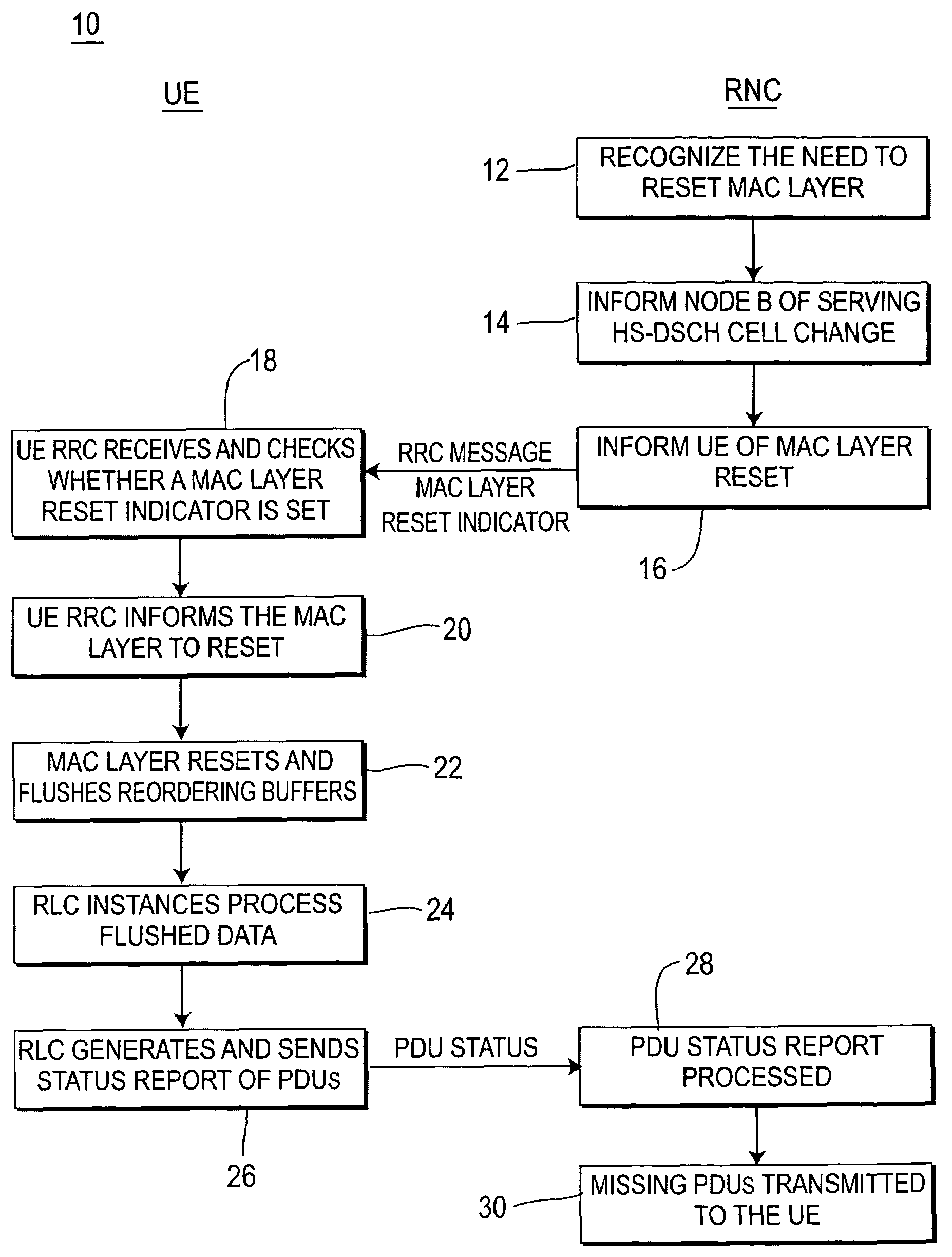
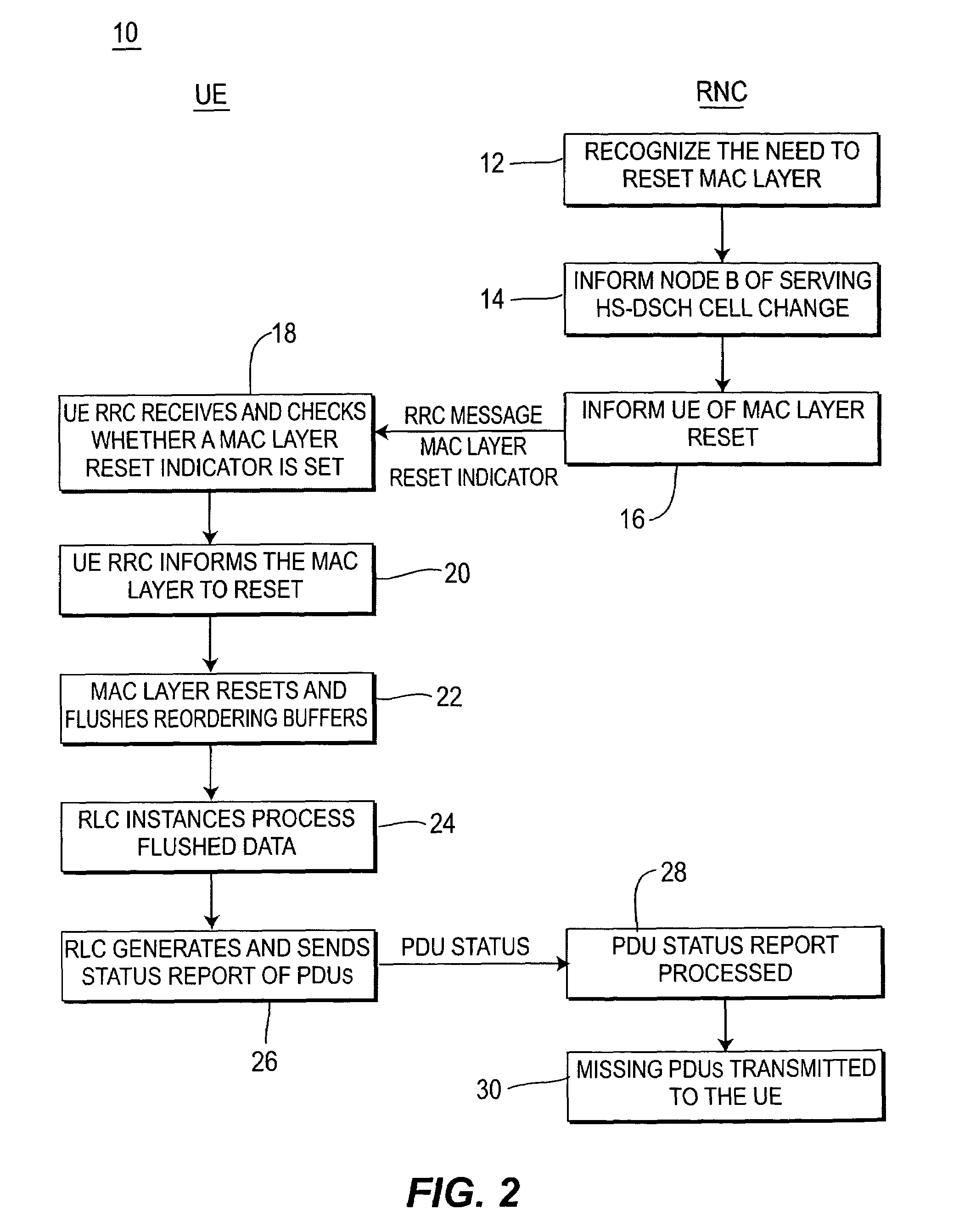
[0019]The present invention is a method and system for the UE and RNC to perform a series of actions in order to reduce transmission latency and potentially prevent loss of PDUs upon a MAC layer reset. UE generation of the status PDU is coupled with the MAC layer reset. The RNC generates a signaling message with a MAC reset indication. Following the MAC layer reset due to reception of a MAC layer reset request, all PDUs stored in the UE MAC layer reordering buffers are flushed to RLC entities and then processed by RLC entities prior to the generation of a PDU status report. The PDU status report provides the status of all successfully received PDUs to the RNC. This provides fast generation of a PDU status report. Upon reception of a PDU status report in the RNC, missing PDUs are realized and retransmitted to the UE.

Problems solved by technology

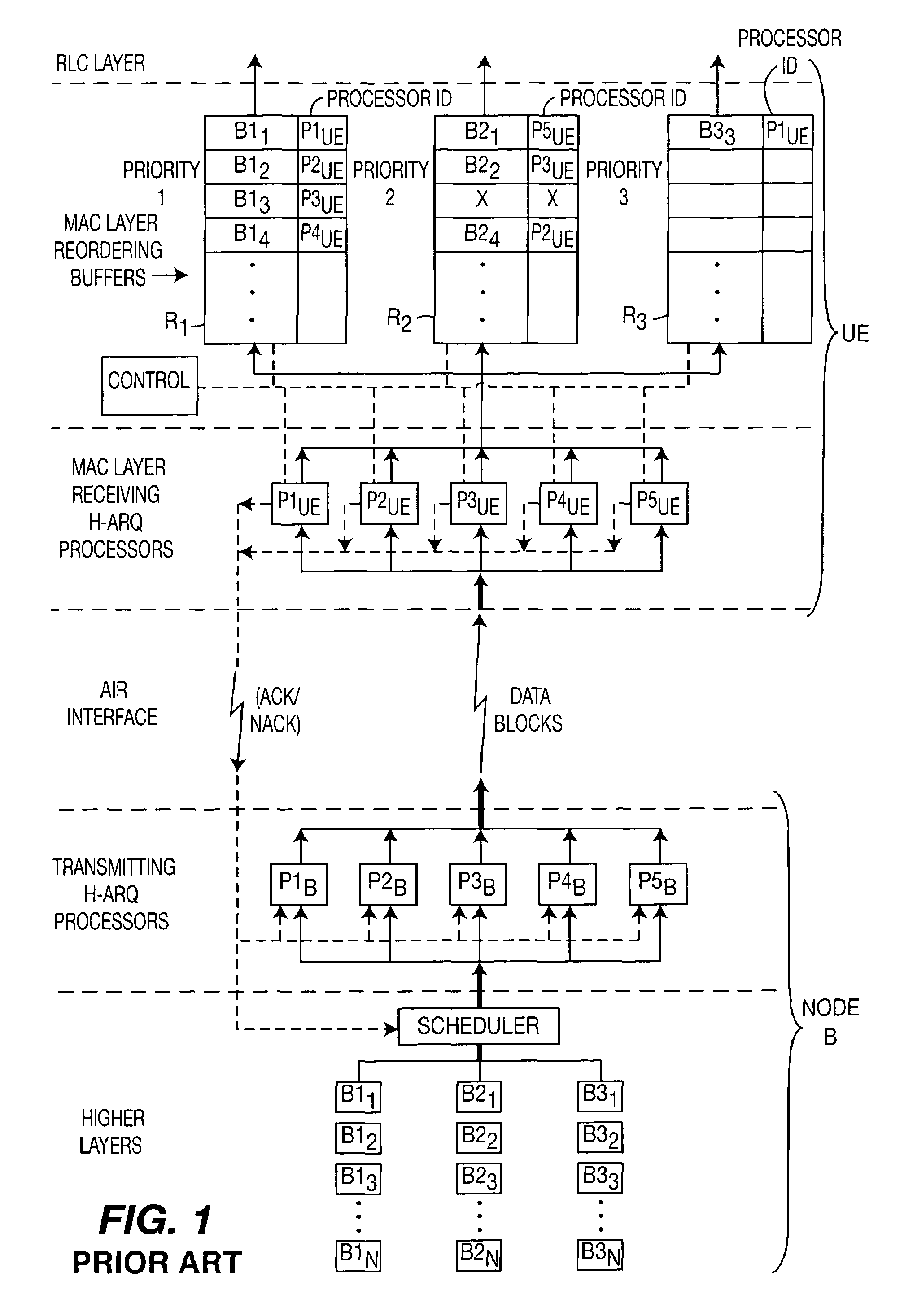
However, for the high speed channels of 3G cellular systems, data is distributed by the Node B. One of these high speed channels, for example, is the High Speed Downlink Shared Channel for transmission in Node B. When the distributing entity (Node B) to which the UE is attached changes, there is a potential loss of data buffered in the distributing entity.
If the generation of the Status PDU is delayed, as a consequence, the latency of data retransmission may be large and may not satisfy QoS requirements.
Since the source Node B performs scheduling and buffering of the data, and since the data rates are very high, (for example 10 Mb / sec or higher), when the UE performs a serving HS-DSCH cell change (especially for an Inter-Node B handover) there is a possibility that considerable amounts of data buffered in the source Node B will be lost.
In either of these two cases, if data buffered in the source Node B needs to be recovered, then a status PDU will be processed, but proper reception of data retransmitted by the UE will be considerably delayed.
This is due to delayed generation of the status PDU by the UE and reception of the status PDU in the RNC.
This not only results in a delay of the transmission, but requires the UE to have a memory capable of data buffering for continuous data reception until the missed data can be successfully retransmitted.
Since memory is very expensive, this is an undesirable design constraint.
Another problem encountered with handover is the data that is buffered within the UE.

Method used


Image

  • System for efficient recovery of Node-B buffered data following MAC layer reset
  • System for efficient recovery of Node-B buffered data following MAC layer reset
  • System for efficient recovery of Node-B buffered data following MAC layer reset

Examples


first embodiment

[0025]Referring to the flow diagram of FIG. 2, the present invention which comprises a method 10 of determining the status of the PDU transmissions to the UE with minimal delay following a MAC layer reset condition is shown. The procedure commences with the RNC recognizing the need to reset the UE MAC layer (step 12).

[0026]One possible cause for a UE MAC layer reset is in the event of a serving HS-DSCH cell change. The RNC informs the Node B of the HS-DSCH cell change (step 14) in the case of an Inter-Node B serving HS-DSCH cell change, and also in the case of an Intra-Node B serving HS-DSCH cell change where the source Node B is the same as the target Node B, but where transmission queues cannot be rerouted from the source to target cell. In both of these cases, a MAC reset is required. Along with the HS-DSCH cell change indication, the UE is informed of the MAC layer reset requirement by the RNC, as indicated via a Radio Resource Control (RRC) message (step 16). It should be noted...

second embodiment

[0039]the present invention comprises a method 40 for determining the status of PDU transmissions to the UE with minimal delay following a MAC layer reset condition and is shown in FIG. 3. After the RNC recognizes the need for a MAC layer reset (step 12) and the Node B and UE are notified (steps 14 and 16), the RNC halts all downlink HS-DSCH transmissions (step 17). Note that step 17 may occur in advance of step 14 or 16 without any adverse consequences. The RNC subsequently receives the PDU status report (step 32). The PDU status report indicates the PDUs lost as a result of the MAC reset and potentially additional PDUs lost in the source Node B the case of an HS-DSCH cell change. The PDU status report is then processed (step 34) and the missing PDUs are retransmitted to the UE (step 36). The RNC initiates transmission in the new cell by scheduling transmission of lost PDUs that require retransmission first. The RNC then resumes PDU transmissions (step 38) at the point where transm...

third embodiment

[0040]Referring to FIG. 4, a method 50 in accordance with the present invention is shown. This method 50 is similar to the method 40 shown in FIG. 3. However, instead of restarting the downlink HS-DSCH transmissions to the UE in response to the receipt of a PDU status report at step 32 as shown in FIG. 3, the method 50 of this embodiment of the present invention restarts transmissions upon the receipt of a “trigger”, or a predetermined event (step 19). In a first example, the trigger may comprise the establishment of the transport channel in UTRAN which, as would be understood by those of skill in the art, is accomplished by an RNC with the new “target” Node B signaling procedure. The reception in the RNC of a confirmation generated by the Node B is used as the trigger.

[0041]In a second example, the trigger may comprise reception or detection of the “in-sync” indication. Upon establishment of dedicated resources in the target Node B, an “in-sync” indication may be determined in the ...


PUM


Abstract

A method and system for the UE and RNC to reduce transmission latency and potentially prevent loss of PDUs upon a MAC layer reset. UE generation of the status PDU is coupled with the MAC layer reset. The RNC generates a message with a MAC reset indication. Following the MAC layer reset all PDUs stored in the UE MAC layer reordering buffers are flushed to RLC entities and then processed by RLC entities prior to the generation of a PDU status report. The PDU status report provides to the RNC the status of all successfully received PDUs. Upon reception of a PDU status report in the RNC, missing PDUs are realized and retransmitted to the UE.

Description

CROSS REFERENCE TO RELATED APPLICATION(S)[0001]This application claims priority from U.S. Provisional Patent Application No. 60 / 410,737 filed Apr. 5, 2002, which is incorporated by reference as if fully set forth.FIELD OF INVENTION[0002]The present invention relates to the field of wireless communications. More specifically, the present invention relates to efficient recovery of data transmission between a pair of Layer 2 automatic repeat request (ARQ) peer entities following MAC layer reset of an intermediate node from where data transmissions are distributed. One such example of this handover scenario is a system employing hybrid ARQ (H-ARQ) and adaptive modulation and coding (AM&C) techniques.BACKGROUND[0003]A third generation (3G) Universal Terrestrial Radio Access Network (UTRAN) comprises several radio network controllers (RNCs), each of which is associated with one or more Node Bs, and each Node B is associated with one or more cells.[0004]The 3G FDD and TDD systems typically...

Claims


Application Information

Patent Timeline
IPC IPC(8): H04J3/22H04N7/173C07C67/52C07C67/54C07C69/82G02B26/10G03B11/00G03B17/02G06F1/16G06F11/10G06F15/00G06K17/00G06K19/00G06T9/00G09C1/00G09G3/02G10L19/00G11B20/10G11B20/14G11B20/18G11B20/22H03L7/091H03M13/03H03M13/13H03M13/23H03M13/29H04B7/005H04B7/24H04B7/26H04B14/00H04B17/00H04H60/72H04J13/16H04L1/00H04L7/00H04L9/08H04L9/10H04L9/32H04L12/28H04L12/54H04L25/03H04L25/49H04L25/497H04L27/10H04L27/156H04L27/18H04L47/765H04L69/40H04M1/66H04M1/72415H04M3/22H04N5/225H04N5/38H04N5/44H04N5/46H04N5/64H04N5/66H04N5/74H04N5/76H04N5/765H04N5/775H04N5/85H04N5/907H04N5/92H04N7/01H04N7/08H04N7/16H04N7/26H04N7/36H04N7/52H04N9/31H04N9/64H04N9/79H04N9/804H04N17/00H04N21/41H04N21/414H04Q3/00H04W4/06H04W4/10H04W4/12H04W4/14H04W4/16H04W8/02H04W8/06H04W8/08H04W8/16H04W8/20H04W8/24H04W8/26H04W12/06H04W12/10H04W24/00H04W28/04H04W36/02H04W36/04H04W36/18H04W36/30H04W40/22H04W56/00H04W72/04H04W72/12H04W76/02H04W76/06H04W80/06H04W84/08H04W84/12H04W88/02
CPCH04L1/1685H04L1/1841H04W36/02H04L65/4061H04L65/1043H04L61/2553H04L51/28H04L51/38G06F1/1626G06F1/1639G06F21/305G06F21/6209G06F21/74G06F21/88G11B20/10009G11B20/10425H03L7/091H04B7/2628H04B10/25754H04J13/0077H04J13/16H04L1/0066H04L1/0068H04L9/085H04L9/304H04L12/4641H04L12/5695H04L25/03038H04L25/4902H04L25/4904H04L25/497H04L27/156H04L29/06027H04L29/12471H04L63/126H04L65/1006H04M1/72533H04M7/1295H04N1/00957H04N1/32106H04N1/40H04N5/2251H04N5/2257H04N5/4401H04N5/4448H04N5/46H04N5/64H04N5/76H04N7/0112H04N7/163H04N7/17327H04N9/3129H04N9/642H04N9/7925H04N21/2543H04N21/4181H04N21/433H04N21/4623H04N21/47211H04N21/6175H04N21/6187H04N21/6582H04Q3/0025H04W4/14H04W12/10H04W28/00H04W52/30H04W76/022H04W84/08H04L41/06H04L47/72H04L47/745H04L47/765H04L47/15H04L47/822H04L47/824H04W36/0072H04N19/139H04N19/70H04N19/51H04N19/109H04N19/91H04N19/527H04N19/517H04N19/625H04W28/04H04L65/1016H04N2201/3212H04L43/0829G11B20/22H04L51/04H04M3/42221H04N5/38H04N5/445H04N5/45H04N5/66H04N5/775H04N5/85H04N5/907H04N7/0122H04N9/8042H04W4/10H04W4/12H04W8/245H04W8/26H04W28/18H04W28/26H04W40/00H04W72/042H04W76/005H04W76/02H04W76/06H04W88/085H04W88/16G06F2221/2105G06F2221/2115H04N2201/0094H04N2201/3274H04N2201/3222Y10S707/99943Y10S370/906Y10S370/907H04L47/70H04W76/45H04W76/30H04W76/12H04W76/10H04N21/426H04M1/72415H04L51/48H04L51/58H04L65/1104H04N23/50H04N23/57H04W72/23H04L49/90H04L1/18H04L65/1101H04L1/1812H04W36/04
Inventor TERRY, STEPHEN E.CHAO, YI-JU
Owner APPLE INC
Learn More