Drive device for window wipers with a parking position switch

a technology of driving device and windshield wiper, which is applied in the direction of motor/generator/converter stopper, dynamo-electric converter control, vehicle cleaning, etc., can solve the problems of reducing the life of the gear, significant design limits, and increasing mechanical tension, so as to avoid mechanical damage, not susceptible to malfunction, and the effect of variable design

Inactive Publication Date: 2010-05-04
ROBERT BOSCH GMBH
View PDF9 Cites 35 Cited by
  • Summary
  • Abstract
  • Description
  • Claims
  • Application Information

AI Technical Summary

Benefits of technology

[0011]Thus, in a drive device of the above-described type with a park position switch according to the invention it is first of all provided that the sleeve is embodied as a contact sleeve for contacting the contacts mounted for rotation, such that contact tracks are provided on the contact sleeve, and at least one of the contact tracks is disposed on the inner surface of the contact sleeve. It is furthermore provided that the driving means comprises a driving disk having a centrally mounted cylindrical member and contact lugs, such that at least one of the contact lugs is formed on the surface of the cylindrical member. According to the invention, the cylindrical member extends into the contact sleeve, so that the contact lugs of the driving disk, which rotates together with the output gearwheel, slidingly engage the contact tracks of the contact sleeve. This results in a park position switch with a snow load safety mechanism that is space saving, has high contact stability and is variable in design. In particular, it is possible according to the invention to essentially integrate the park position switch contact system comprising the contact tracks and the contact lugs into the gear cover.
[0012]A particularly advantageous embodiment of this drive device provides for three contact tracks on the contact sleeve and two electrically interconnected contact lugs on the driving disk, which are configured and disposed in such a way that as the driving disk rotates a first contact lug slides continuously on a first contact track and a second contact lug slides alternately on a second and a third contact track of the contact sleeve. This simplified slider system with only two contact lugs is inexpensive and not susceptible to malfunction.
[0014]It is further advantageous if all three contact tracks are disposed on the inner surface of the contact sleeve and, accordingly, both contact lugs are formed on the surface of the cylindrical member.
[0016]For a contactability that is simple to realize from a production standpoint, it is advantageous in this and other embodiments if the first contact track is formed on the inner end face of the contact sleeve and the associated first contact lug on the top surface of the cylindrical member.

Problems solved by technology

This has the result that the wiper is again driven against the obstacle and mechanical tension builds again.
This obviously causes substantial loading of the gear and thereby reduces the life of the gear.
This conventional parallel configuration places significant limits on the design and is also not fully satisfactory in other respects.

Method used


Image

  • Drive device for window wipers with a parking position switch
  • Drive device for window wipers with a parking position switch
  • Drive device for window wipers with a parking position switch

Examples


Embodiment Construction

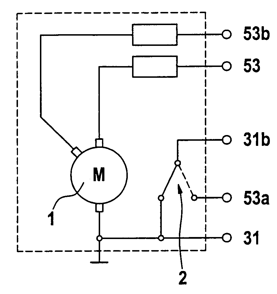
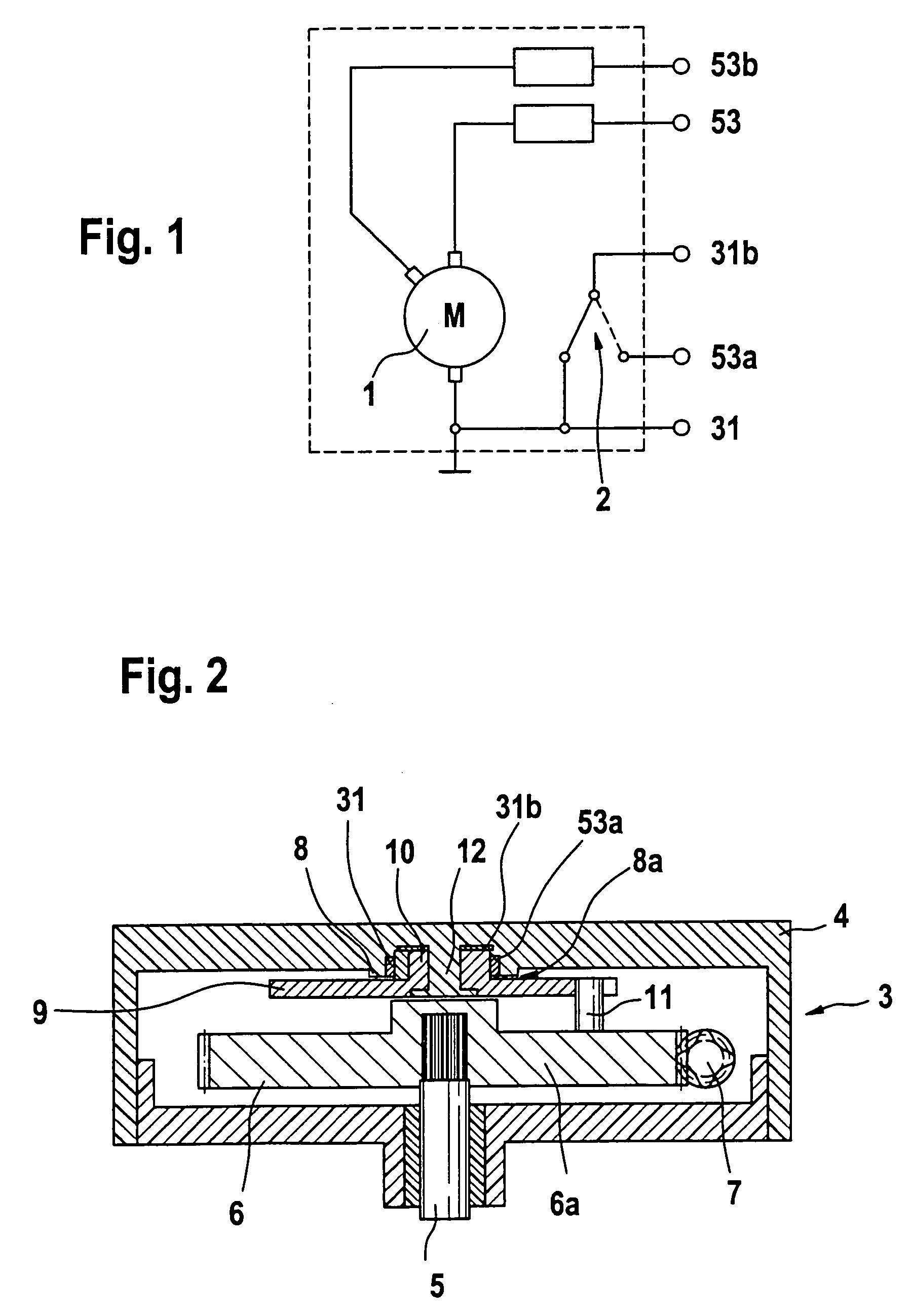
[0032]FIG. 1 is a circuit diagram illustrating the electrical functions of a park position switch of a windshield wiper drive for cleaning a windshield of a motor vehicle. The figure shows an only schematically indicated electric drive motor 1, which has three electrical connections. A ground connection runs to a terminal 31 and thus to a negative pole of a vehicle battery (not depicted) or to a vehicle ground. A terminal 53 leads to a positive pole of the vehicle battery via a steering column switch (not depicted) if the drive motor 1 is to run in a first, i.e., a slower gear. If the drive motor 1 is to be operated in a faster, second gear, a shunt winding of the drive motor 1 is additionally connected to a terminal 53b, as depicted.

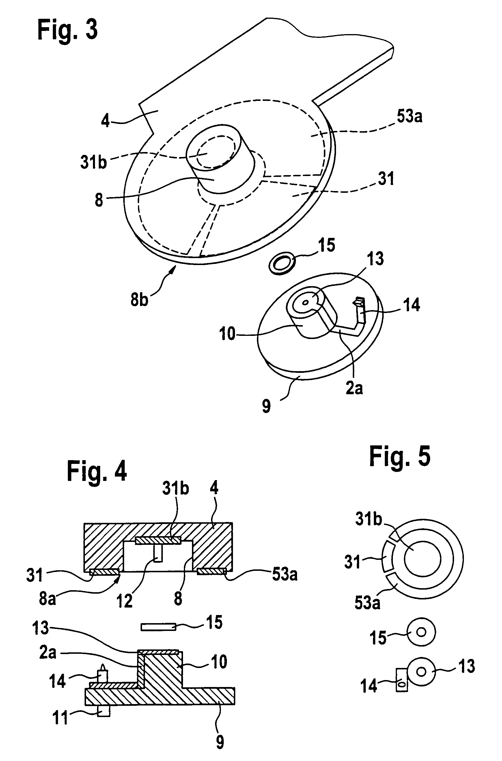
[0033]The park position switch, which is also depicted in FIG. 1, is intended to ensure reliable and exact placement of the wiper in the park position. This switch is essentially realized by a contact system that has three contact tracks 31b, 53a and 31...


PUM


Abstract

The device comprises an output gearwheel (6), a gear cover (4) having a plastic sleeve open toward the output gearwheel (6) and a park position switch having first contacts mounted for rotation and second contacts fixed to the gear cover (4) and a driving means. The invention provides that the sleeve is embodied as a contact sleeve (8) having contact tracks (31b, 53a, 31), particularly along the inner surface of the contact sleeve (8). To enable sliding contact on rotation, the cylindrical member (10) of a driving disk (9) extends into the contact sleeve (8).

Description

BACKGROUND OF THE INVENTION[0001]The invention relates to a drive device for a windshield wiper having an output gear, a gear cover on which is formed a plastic sleeve that is open toward the output gearwheel, and a park position switch comprising first contacts mounted for rotation and second contacts fixed to the gear cover and in sliding contact with the first contacts, such that the contacts mounted for rotation are connected to the output gear via a driving means.[0002]A drive device of this type is disclosed in German Laid Open Application DE 195 48 824 A1.[0003]Drive devices for windshield wipers have switches that ensure that the motor of the drive device continues to be supplied with current after the driver opens the master switch until the windshield wiper has returned to its initial position, which is also referred to as the park position. Accordingly, the switch is called the park position switch.[0004]The park position switch is conventionally implemented as a switchin...

Claims


Application Information

Patent Timeline
Patent Type & Authority Patents(United States)
IPC IPC(8): A47L1/00B60S1/08B60S1/16
CPCB60S1/166B60S1/08B60S1/06B60S1/16
Inventor HAWIGHORST, ACHIMSTUBNER, ARMIN
Owner ROBERT BOSCH GMBH
Why Eureka
Try Eureka