

Footwear with a sole structure incorporating a lobed fluid-filled chamber
a technology of fluid-filled chambers and sole structures, applied in the field of feet, can solve problems such as the decrease of foam compressibility
- Summary
- Abstract
- Description
- Claims
- Application Information
AI Technical Summary
Benefits of technology
Problems solved by technology
Method used
Image

Examples
Embodiment Construction
Introduction
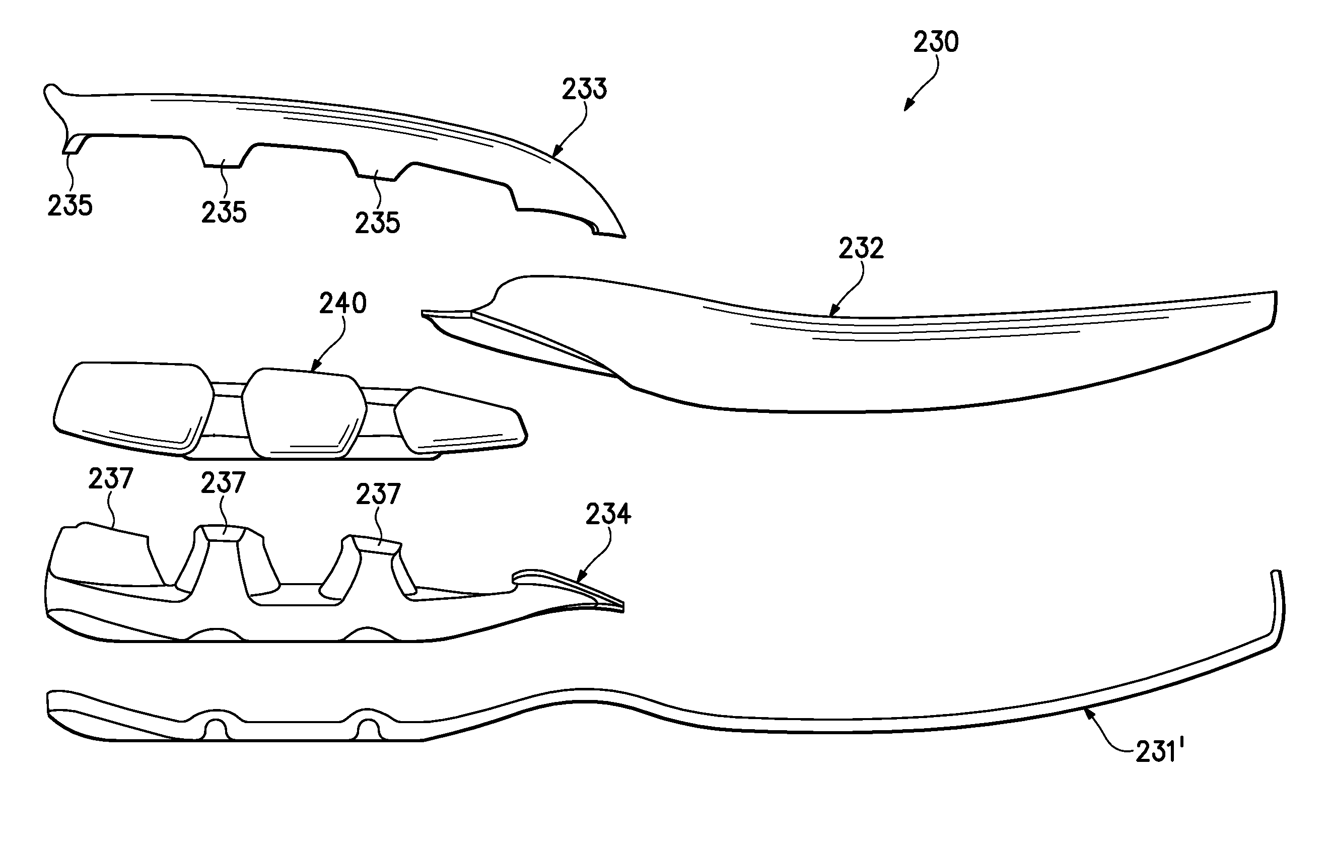
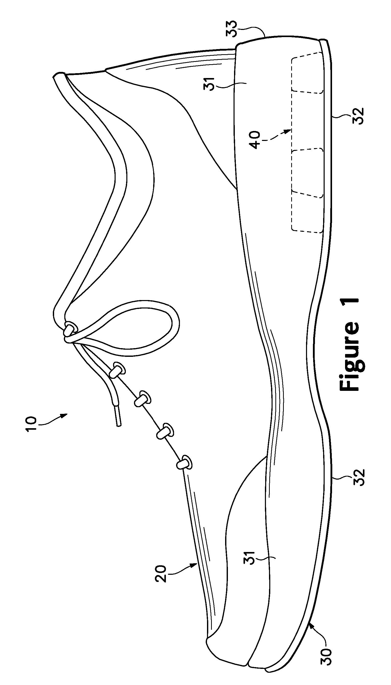
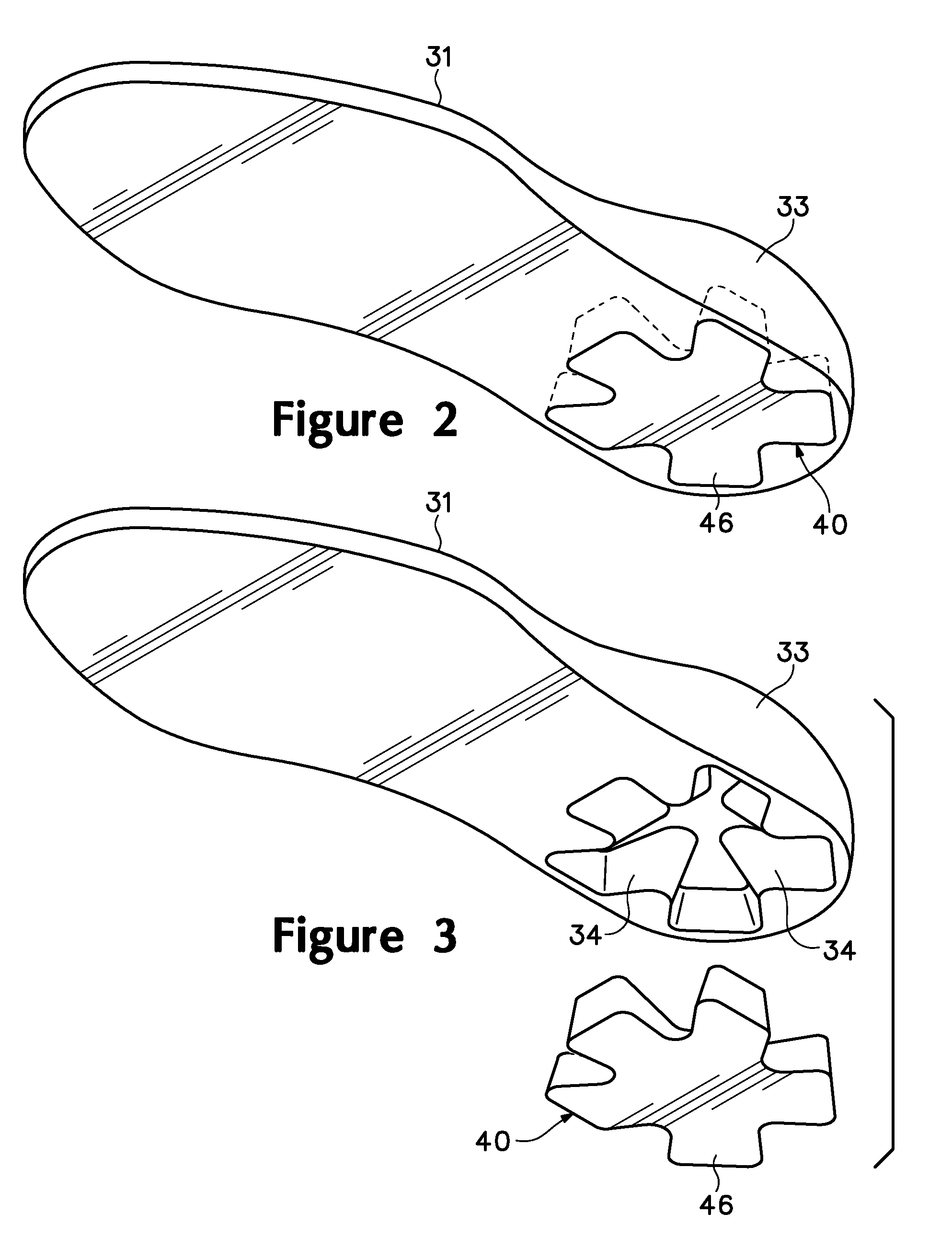
[0075]The following discussion and accompanying figures disclose articles of athletic footwear incorporating fluid-filled chambers in accordance with the present invention. Concepts related to the footwear, and more particularly the fluid-filled chambers, are disclosed with reference to footwear having a configuration that is suitable for running. The invention is not solely limited to footwear designed for running, however, and may be applied to a wide range of athletic footwear styles, including basketball shoes, cross-training shoes, walking shoes, tennis shoes, soccer shoes, and hiking boots, for example. In addition, the invention may also be applied to non-athletic footwear styles, including dress shoes, loafers, sandals, and work boots. Accordingly, one skilled in the relevant art will appreciate that the concepts disclosed herein apply to a wide variety of footwear styles, in addition to the specific style discussed in the following material and depicted in the a...
PUM
| Property | Measurement | Unit |
|---|---|---|
| pressure | aaaaa | aaaaa |
| pressure | aaaaa | aaaaa |
| pressure | aaaaa | aaaaa |
Abstract
Description
Claims
Application Information