
Sequencing device for deploying a structure as a function of the kinematics of one mobile body thereof

a technology of aqueous device and a mobile body, which is applied in the direction of electrochemical generators, collapsible antennas, batteries, etc., can solve the problem that the sequencer is not able to initiate the deployment of a body

Active Publication Date: 2010-05-04
ALCATEL LUCENT SAS
View PDF15 Cites 15 Cited by
  • Summary
  • Abstract
  • Description
  • Claims
  • Application Information

AI Technical Summary

Benefits of technology

Enables kinematic releases in intermediate deployment steps without a locking state indication, allowing the deployment of bodies even if the attached body has not completed its deployment, enhancing the deployment efficiency of structures like solar generators and telecommunication antennas on spacecraft.

Problems solved by technology

Thus this kind of sequencing device is not able to initiate the deployment of a body if the deployment of the body to which it is attached has not been completed, because it necessitates a locked state of the body that is being deployed and an element for indicating that locked state.

Method used


Image

  • Sequencing device for deploying a structure as a function of the kinematics of one mobile body thereof
  • Sequencing device for deploying a structure as a function of the kinematics of one mobile body thereof
  • Sequencing device for deploying a structure as a function of the kinematics of one mobile body thereof

Examples


first embodiment

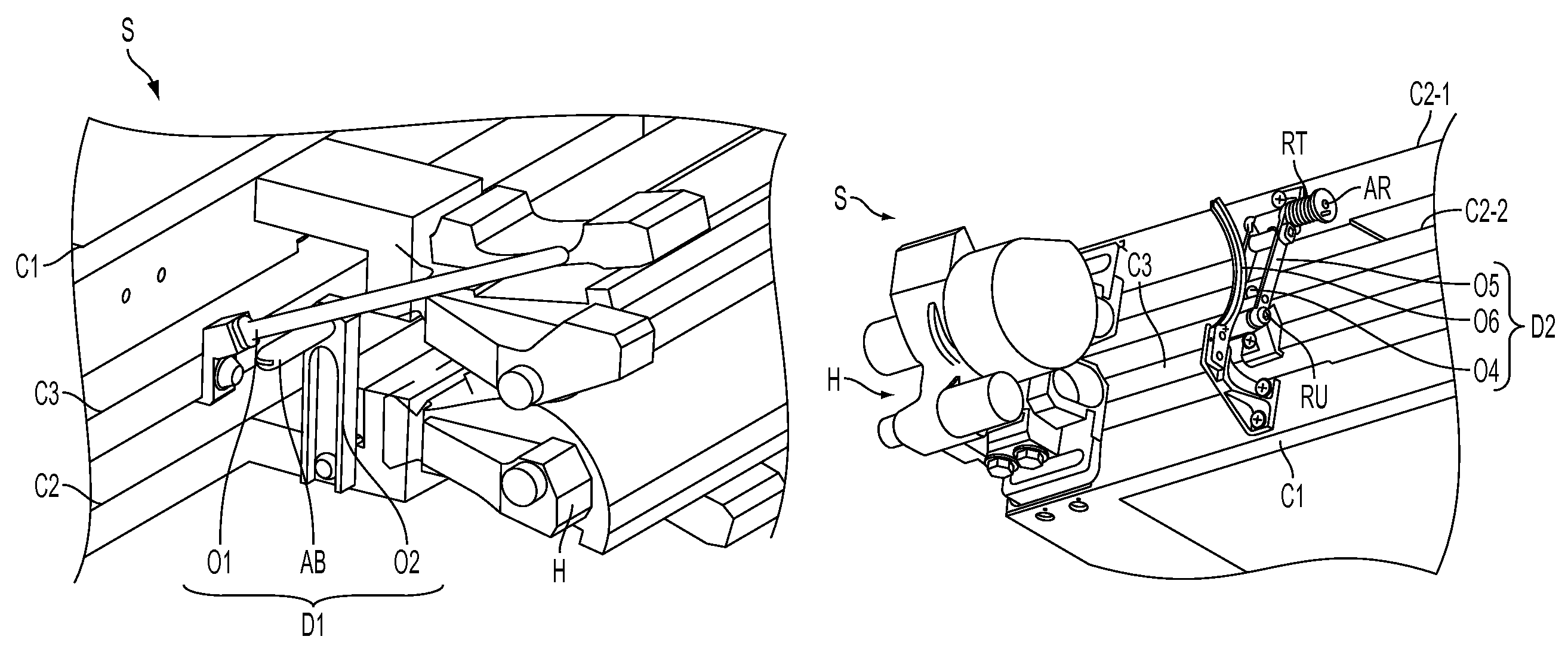
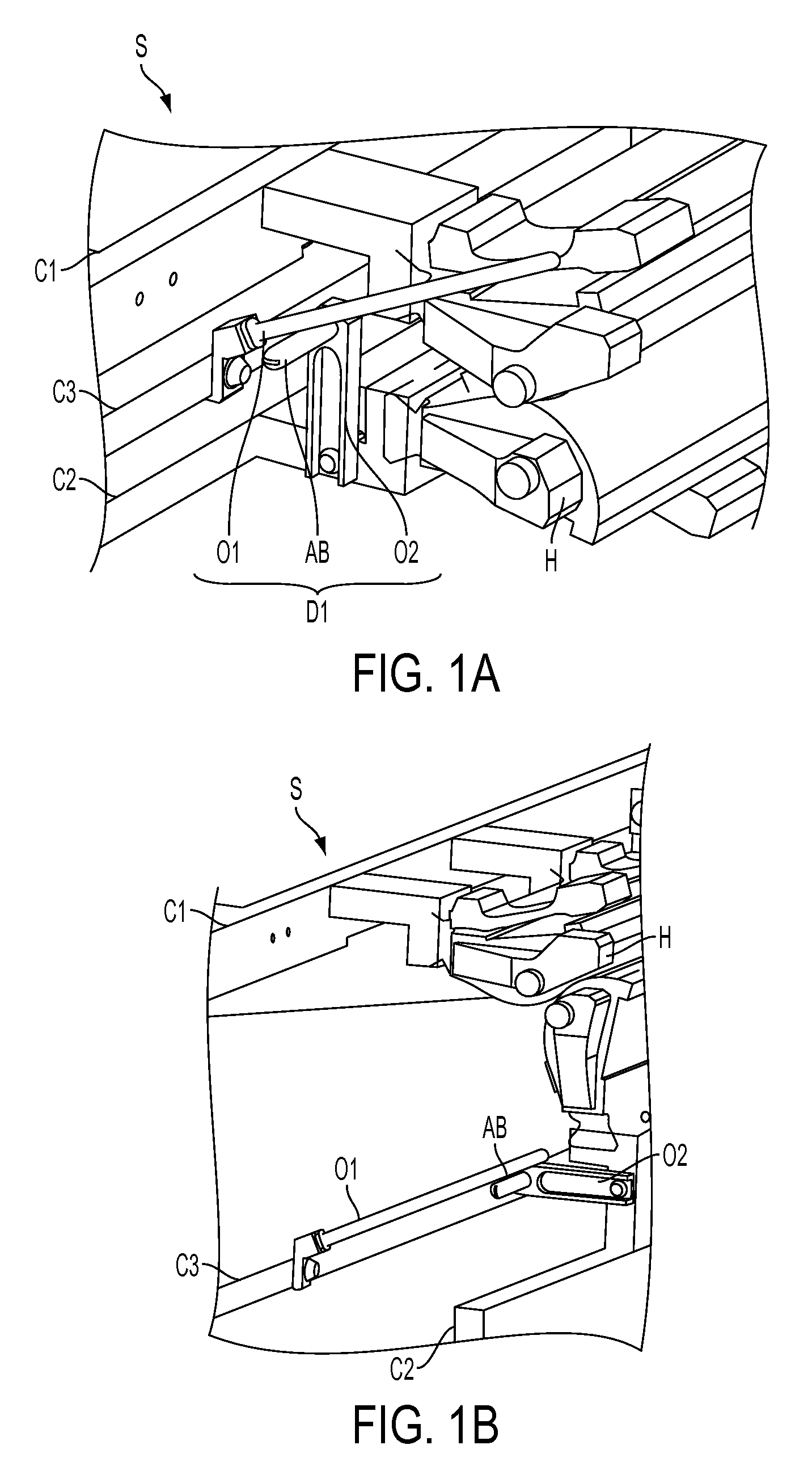
[0036]a sequencing device of the invention is described first with reference to FIGS. 1A to 1C.

[0037]The structure S shown in part in FIGS. 1A to 1C comprises a first body C1 constituting the panel of a central pylon of a satellite, for example, a second body C2 mounted so as to be mobile relative to the first body C1 by virtue of an articulation H and constituting another panel, and a third body C3 that is mounted so as to be mobile relative to the second body C2 by virtue of another articulation (not shown) and constituting a further panel.

[0038]As shown in FIG. 1A, in the folded state of the structure S, which constitutes its initial state, the three bodies C1 to C3 are substantially parallel to each other with the third body C3 interleaved between the first body C1 and the second body C2.

[0039]The structure S is further equipped with a sequencing device D comprising a first member O1 fixedly mounted on the third body C3 and a second member O2 mounted on the second body C2 and co...

second embodiment

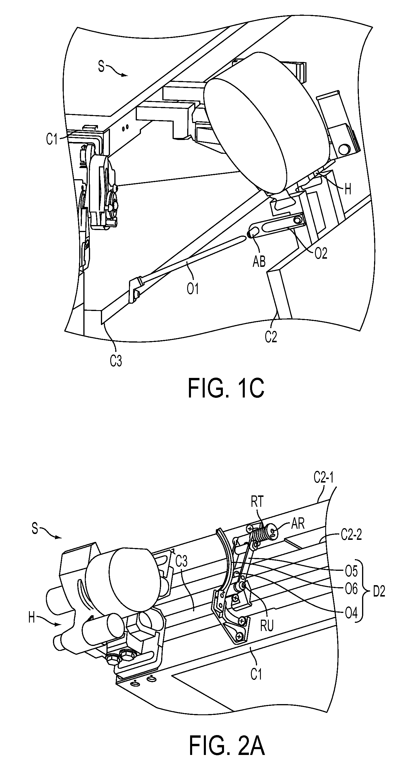
[0048]a sequencing device of the invention is described next with reference to FIGS. 2A to 2C.

[0049]The structure S shown in part in FIGS. 2A to 2C again comprises a first body C1 constituting the panel of a central pylon of a satellite, for example, a second body C2-1 that is mounted so that it is mobile relative to the first body C1 by virtue of an articulation H and which constitutes another panel, a third body C3 that is mounted so that it is mobile relative to the second body C2-1 by virtue of another articulation (not shown) and which constitutes a further panel, and a fourth body C2-2 that is mounted so that it is mobile relative to the second body C2-1 by virtue of another articulation (not shown) and which constitutes a further panel.

[0050]As shown in FIG. 2A, in the folded state of the structure S, which constitutes its initial state, the four bodies C1 to C3 are substantially parallel to each other with the third body C3 interleaved between the first body C1 and the secon...


PUM


Abstract

A device is disclosed for sequencing the deployment of a deployable structure comprising a first body, at least one second body mobile relative to the first body, and at least one third body mobile relative to either the first body or the second body and disposed, in an at least partially folded position of the structure, against or between the first and second bodies. The device comprises a first member fixedly mounted on the third body and preventing its deployment when it is immobilized and a second member mounted on the second body and immobilizing the first member until the second body has effected a selected portion of a kinematic that drives it from an initial position to a final position.

Description

CROSS-REFERENCE TO RELATED APPLICATIONS[0001]This application is based on French Patent Application No. 03 15 224 filed Dec. 23, 2003, the disclosure of which is hereby incorporated by reference thereto in its entirety, and the priority of which is hereby claimed under 35 U.S.C. §119.BACKGROUND OF THE INVENTION[0002]1. Field of the Invention[0003]The field of the invention is that of structures with deployable bodies, and to be more precise sequencing devices controlling at least in part the deployment of mobile bodies of such structures.[0004]2. Description of the Prior Art[0005]In the aerospace field, for example, certain structures are deployed when the craft (or platform) on which they are installed have reached their operating location (as in the case of a sensing or telecommunication satellite), or have effected a certain portion of their track or mission (as in the case of a spacecraft). This deployment, for example of solar panels of a solar generator and / or send and / or rece...

Claims


Application Information

Patent Timeline
Patent Type & Authority Patents(United States)
IPC IPC(8): B64G1/44B64G1/22B64G1/50B64G1/64B64G1/66H01L31/042H01Q1/08
CPCB64G1/222B64G1/64B64G1/503B64G1/443Y10S136/292B64G1/2224
Inventor CHAIX, RODOLPHEDAVAL, CHRISTIAN
Owner ALCATEL LUCENT SAS
Learn More