Airbag assembly

a technology of airbags and assemblies, applied in the direction of vehicle components, pedestrian/occupant safety arrangements, vehicular safety arrangments, etc., can solve the problems of occupants being seriously injured or even killed, and the airbag inflating can exercise a considerable force on the occupants, and still a residual risk

Inactive Publication Date: 2010-05-04
FAURECIA INNENRAUM SYST
View PDF21 Cites 0 Cited by
  • Summary
  • Abstract
  • Description
  • Claims
  • Application Information

AI Technical Summary

Benefits of technology

[0010]The widening of the chute into a side direction has the effect that the airbag is filled out at its sides ahead of its middle region when it is deployed into the passenger compartment. By pushing the airbag to an outer area, the maximum force onto an occupant located directly in front of the airbag is reduced, thus reducing the risk of injury. The reduction of the maximum force allows placing a child in front of the airbag.
[0013]The at least one sloped sidewall has the effect that the gas flow streaming into the airbag when it is deployed into the passenger compartment is directed such that the sides of the airbag are filled out ahead of the middle region of the airbag.

Problems solved by technology

However, the inflating airbag can exercise a considerable force onto the occupant.
In such instances, the airbag may cause considerable harm or even death to the front facing child.
However, there is still a residual risk in case the driver has inadvertently forgotten to switch off the airbag system when the child is placed in front of the airbag.
Another risk of such systems is that the airbag needs to be reactivated when an adult is placed in front of the airbag which may also be forgotten by the driver.
However, this system requires a special child safety seat.

Method used


Image

  • Airbag assembly
  • Airbag assembly
  • Airbag assembly

Examples


Embodiment Construction

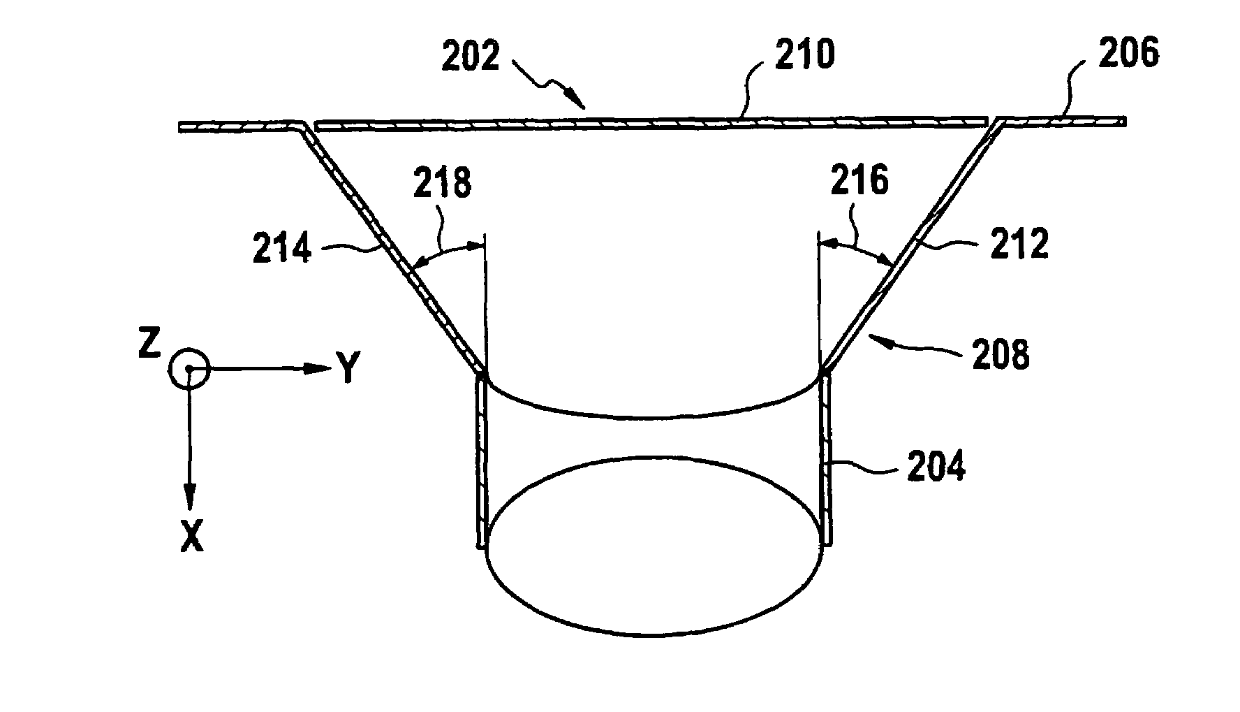
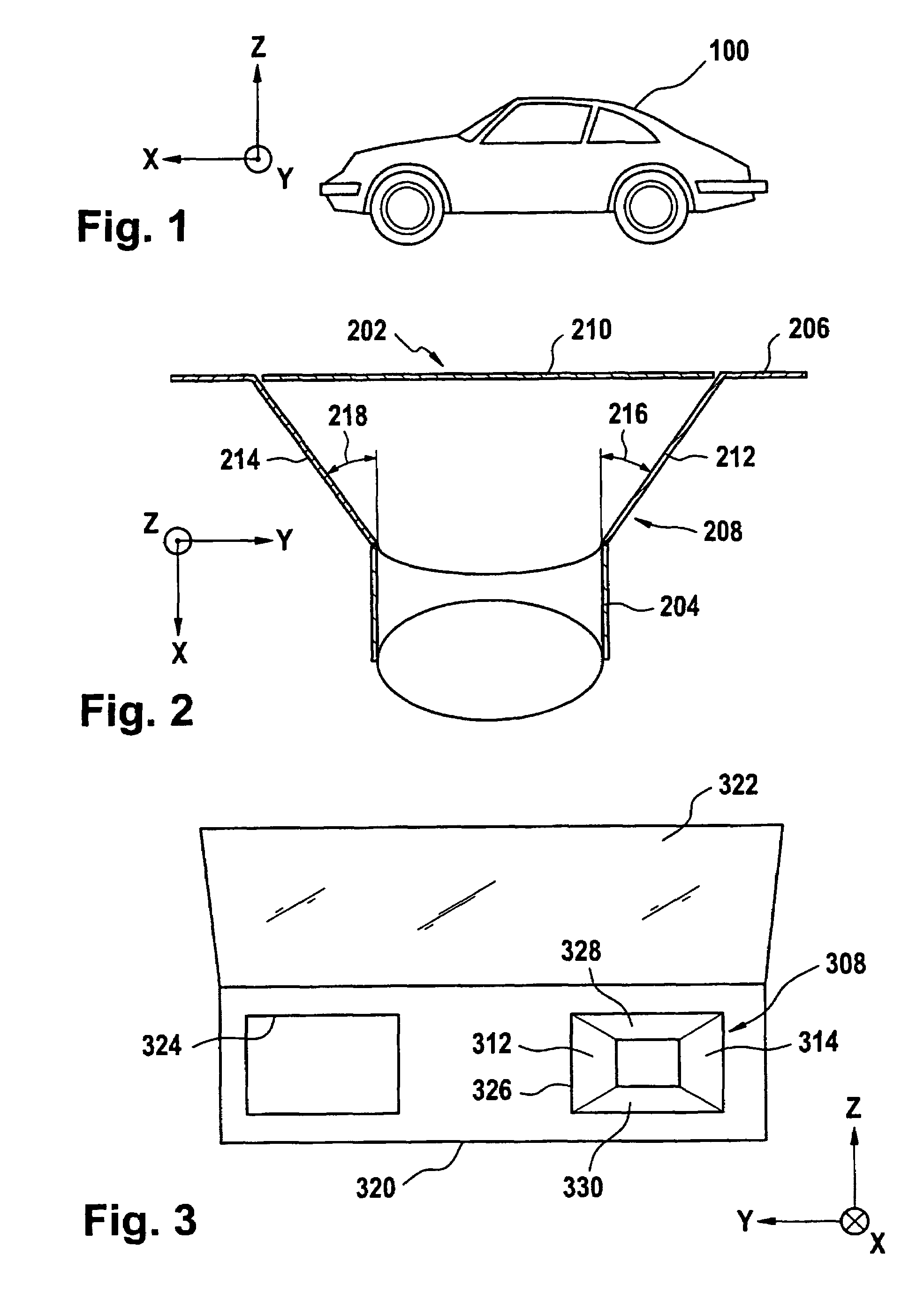
[0028]FIG. 1 shows a side view of an automotive vehicle 100. The automotive vehicle 100 defines a coordinate system, i.e. a forward or x-direction, a side or y-direction and a vertical or z-direction as shown in the coordinate system depicted in FIG. 1. This coordinate system is referenced throughout the following FIGS. 2 to 7. Like reference numerals are used to designate like parts in the Figs.

[0029]FIG. 2 shows a schematic cross-sectional view of an airbag assembly 202 that can be mounted in automotive vehicle 100 (cf. FIG. 1). The airbag assembly 202 can be a passenger airbag, a knee airbag, a side airbag or another kind of airbag assembly.

[0030]For the purpose of ease of explanation it is assumed in the following that the airbag assembly 202 is a passenger airbag assembly.

[0031]A folded passenger airbag 204 is arranged below an instrument panel 206 in the interior of the automotive vehicle. The airbag assembly 202 operates by deploying the passenger airbag 204 which expands tow...


PUM


Abstract

The present invention relates to an airbag assembly comprising: a folded airbag adapted to be inflated and deployed into a passenger compartment upon detection of a collision, a chute for guiding the airbag when it is inflated, the chute extending between the folded airbag and a deployment opening, wherein the chute widens into a side direction.

Description

BACKGROUND OF THE INVENTION[0001]The present invention relates to the field of airbag safety systems, and more particularly to an airbag assembly.[0002]Airbag safety systems have come into widespread use in automotive vehicles and trucks. For example, a modern car can have various airbags, such as a driver airbag, passenger airbag, knee airbags, side airbags and / or other airbags.[0003]Such airbag systems comprise an inflatable cushion, commonly referred to as an ‘airbag’ which is stored folded in a storage receptacle and then very rapidly inflated, as with gas from a pyrotechnic gas generator, when a collision of the vehicle is detected by sensors. The airbag is thereby deployed in a position to absorb the impact of the driver or a passenger.[0004]One or more airbag deployment doors normally overlie the airbag receptacle and are forced open when the airbag is inflated to allow deployment of the airbag through the opening created by the door panel movement.[0005]It is critical that t...

Claims


Application Information

Patent Timeline
Patent Type & Authority Patents(United States)
IPC IPC(8): B60R21/217B60R21/16
CPCB60R21/16B60R21/213B60R2021/162B60R2021/161
Inventor LOEW, JEAN-PHILIPPEKWASNIK, KENNETH JOHN
Owner FAURECIA INNENRAUM SYST
Why Eureka
Try Eureka