Floating platform and method of constructing the same

a floating platform and platform technology, applied in the field of platforms, can solve the problems of high cost of equipment and tools required for underwater drilling and installation of posts, and the difficulty of methods, and achieve the effect of improving the safety of the floating platform

Active Publication Date: 2010-05-04
WATERFRONT CONSTR
View PDF29 Cites 6 Cited by
  • Summary
  • Abstract
  • Description
  • Claims
  • Application Information

AI Technical Summary

Problems solved by technology

Shoreline landing structures such as docks have generally been subjects of challenging structural design because of adverse conditions in which they typically must persist.
However, the ground under water is typically soft and structural posts need to extend sufficiently far beneath the ground to provide adequate support for secondary supports and the decking.
Equipment and tools required for underwater drilling and installation of posts could thus be expensive and the methods extremely difficult.
Although these docks are more flexible and easier to construct than those requiring wood posts, the floating docks have given rise to new obstacles.
For example, the amount of material used in such docks results in heavy structures, presenting transport and floating difficulties.
Additionally, in absence of posts in the ground, some floating docks incorporate structural decking, which adds to the complexity of the design and to the weight and price of the material and which limits the options for designs and materials used for decking.
Moreover, since floating docks lack rigid grounded supports at their transverse boundaries, they may lack sufficient torsional rigidity and be vulnerable to instability when subjected to uneven loading on their decking or on their mooring on the sides of the dock.

Method used


Image

  • Floating platform and method of constructing the same
  • Floating platform and method of constructing the same
  • Floating platform and method of constructing the same

Examples


Embodiment Construction

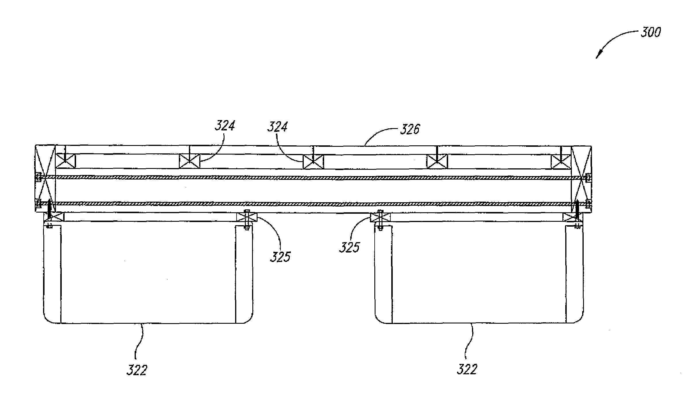
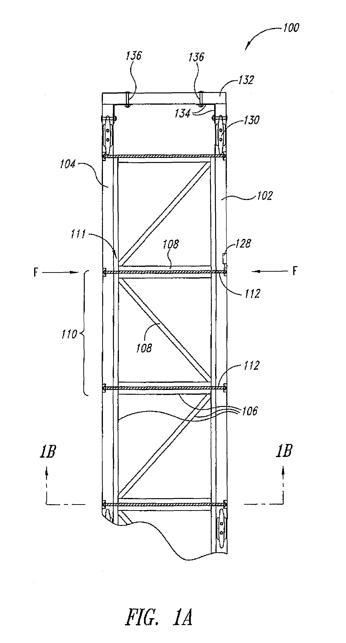
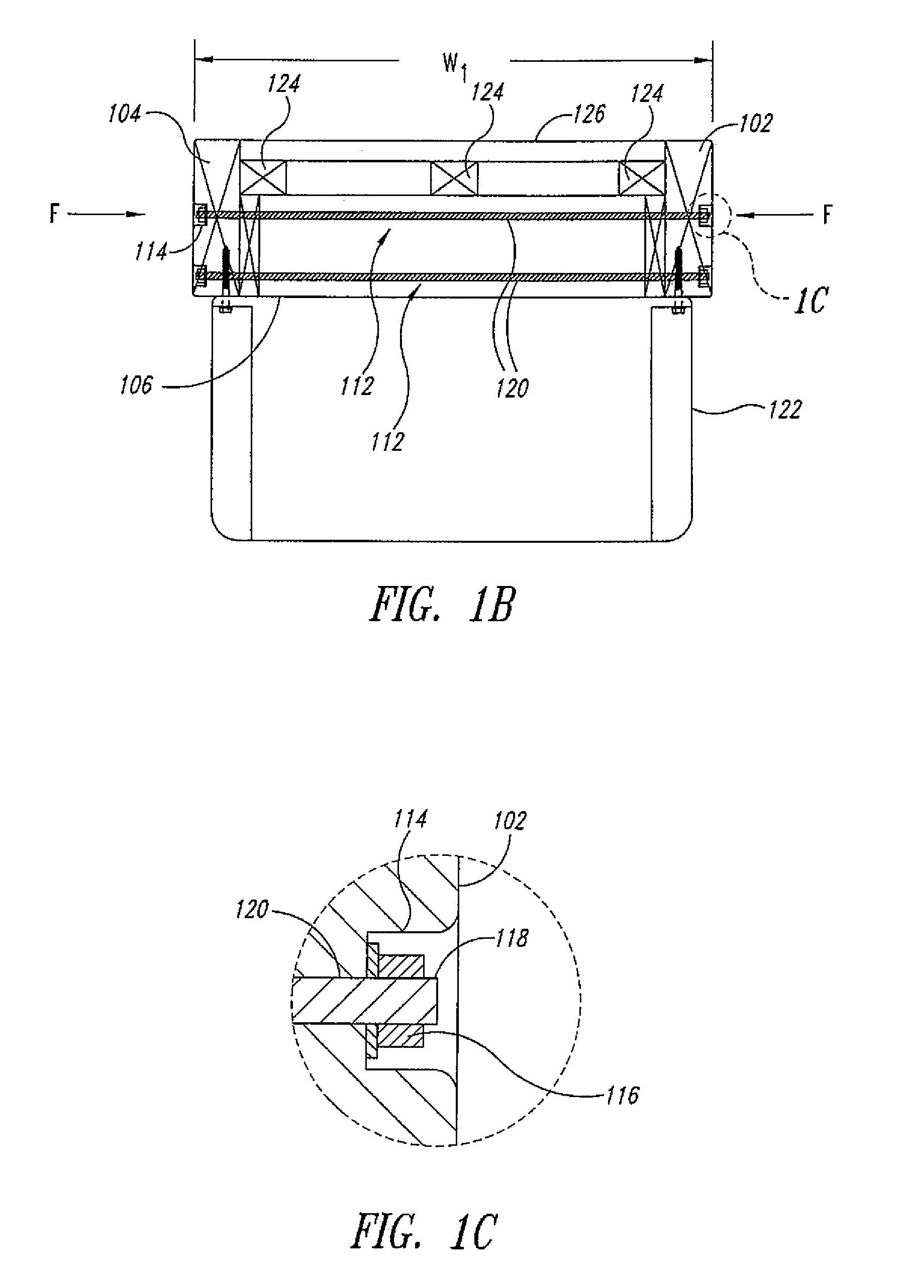
[0020]In one embodiment illustrated in FIG. 1A, a floating platform system 100 includes at least first and second outer longitudinal beam members 102, 104, each typically coinciding with a transverse boundary of the floating platform system 100. The floating platform system 100 further includes at least one truss frame 106 having a plurality of truss elements 108. The truss frame 106 can be one truss frame 106 extending through multiple longitudinal bays 110 or a plurality of truss frames 106, at least one truss frame 106 provided for each longitudinal bay 110. The truss elements 108 form at least one apex 111. The floating platform system 100 of the illustrated embodiment of FIG. 1A illustrates two of a plurality of apices 111 formed by the truss elements 108. The floating platform system 100 also includes at least one biasing device 112 extending in a substantially transverse direction and positioned to apply a force toward at least one of the apices 111.

[0021]The biasing device 1...


PUM


Abstract

A floating platform system comprises first and second outer longitudinal beam members securing a truss frame having a plurality of truss elements. The floating platform system may further include at least one biasing device exerting a force on the longitudinal beam members and / or the truss frame. The floating platform system may further include a platform interface and / or at least one flotation device secured to the longitudinal beam members and / or the truss frame. The floating platform system may further include a plurality of inner longitudinal beam members interposed between the platform interface and / or the flotation device and the outer longitudinal beam members and / or the truss frame.

Description

BACKGROUND OF THE INVENTION[0001]1. Field of the Invention[0002]The present invention is generally related to platforms, and more particularly, to a floating platform system or apparatus and method of making the same.[0003]2. Description of the Related Art[0004]Shoreline landing structures such as docks have generally been subjects of challenging structural design because of adverse conditions in which they typically must persist. Some dock structures involve rows of wooden beams used for decking installed on a frame bed with support posts rooted in the ground beneath the water. However, the ground under water is typically soft and structural posts need to extend sufficiently far beneath the ground to provide adequate support for secondary supports and the decking. Equipment and tools required for underwater drilling and installation of posts could thus be expensive and the methods extremely difficult. Furthermore, such docks are generally rigid and their position does not vary with...

Claims


Application Information

Patent Timeline
Patent Type & Authority Patents(United States)
IPC IPC(8): E01D15/14B63B35/44
CPCB63B9/065E02B3/064B63B35/44B63B75/00
Inventor WILCOX, PAUL E.
Owner WATERFRONT CONSTR
Why Eureka
Try Eureka