Vortex spoiler for delivery of cooling airflow in a turbine engine

a turbine engine and turbine technology, applied in the direction of machines/engines, stators, liquid fuel engines, etc., can solve the problems of reducing the air flow to the components downstream, high heat conditions, and large pressure loss

Inactive Publication Date: 2010-05-04
HONEYWELL INT INC
View PDF19 Cites 25 Cited by
  • Summary
  • Abstract
  • Description
  • Claims
  • Application Information

AI Technical Summary

Benefits of technology

[0008]The present invention provides a vortex spoiler that is configured to deliver cooling air at an exit leading to a plurality of downstream turbine components without a resulting significant pressure loss or creation of tangential stresses.
[0009]In one embodiment, and by way of example only, provided is a vortex spoiler for delivery of a cooling airflow in a turbine engine including a radial exterior sidewall, a radial interior sidewall, a core area, a plurality of inlet ports, a plurality of outlet ports and a plurality of bores. The radial exterior sidewall is positioned to rotate about an axis of rotation. The radial interior sidewall is disposed radially inward of, and surrounded by, the radial exterior sidewall. The core area is coupled between the radial exterior sidewall and the radial interior sidewall, extending inwardly perpendicularly to the axis of rotation. The plurality of inlet ports are formed in and spaced circumferentially about the radial exterior sidewall. The plurality of outlet ports are formed in and spaced circumferentially about the radial interior sidewall. The plurality of bores extend through the core area and define a plurality of ducts that fluidly communicate the inlet ports and the outlet ports. Each of the plurality of ducts is configured such that a cooling airflow may pass radially inwardly with minimal tangential stress and minimal static pressure loss.
[0010]In yet another embodiment, and by way of example only, provided is a gas turbine engine having a compressor section that includes a plurality of rotary compressor stages interconnected by a rotary shaft and a secondary cooling airflow system. The turbine engine includes a collecting chamber arranged to collect pressurized, substantially nonswirling, cooling airflow from the compressor section and a vortex spoiler in fluidic communication with the collecting chamber and interconnected to rotate with the rotary shaft. The vortex spoiler includes a radial exterior sidewall and a radial interior sidewall disposed radially inward of, and surrounded by, the radial exterior sidewall. The vortex spoiler further includes a core area coupled between the radial exterior sidewall and the radial interior sidewall and extending inwardly perpendicularly to the axis of rotation. A plurality of inlet ports are formed in and spaced circumferentially about the radial exterior sidewall. A plurality of outlet ports are formed in and spaced circumferentially about the radial interior sidewall. A plurality of bores are formed through the core area coupling each of the plurality of outlets ports to one of the plurality of inlet ports. The plurality of bores define a plurality of ducts that fluidly communicate the inlet ports and the outlet ports. Each duct of the plurality of ducts is configured such that a cooling airflow may pass radially inwardly with minimal tangential stress and minimal static pressure loss.
[0011]In still another embodiment, and by way of example only, provided is a gas turbine engine including a compressor section including an intermediate pressure compressor and a high pressure compressor; a rotary shaft interconnecting the intermediate pressure compressor and the high pressure compressor in torque transmitting relationship about an axis of rotation; a collecting chamber arranged to collect pressurized, substantially nonswirling, cooling airflow from the compressor section at a location radially outward of the rotary shaft; and a vortex spoiler interconnected to rotate with the rotary shaft and in fluidic communication with the collecting chamber, the vortex spoiler defined by a radial exterior sidewall and a radial interior sidewall disposed radially inward of, and surrounded by the radial exterior sidewall and including a plurality of inlet ports formed in and spaced circumferentially about the radial exterior sidewall and a plurality of outlet ports formed in and spaced circumferentially about the radial interior sidewall, each of the plurality of inlet ports coupled to one of the plurality of outlet ports via a bore, and defining a plurality of ducts that fluidly communicate the inlet ports and the outlet ports, each duct configured having an interior diameter at each of the plurality of inlet ports formed at a preselected angle in a range of approximately 65-75 degrees normal to a surface of the radial exterior sidewall and at each of the plurality of outlet ports having an interior diameter formed at a preselected angle in a range of approximately 15-25 degrees normal to a surface of the radial interior sidewall such that a cooling airflow passes radially inwardly through each of the plurality of ducts with minimal tangential stress and minimal static pressure loss.

Problems solved by technology

Extreme operating conditions generate high temperatures and thus high heat conditions, and high pressure conditions that are known to place increased demands on engine components, manufacturing and technologies.
However, a traditional vortex spoiler having a radially configured profile produces a rather large pressure loss at an exit of a duct that leads to the turbine components being cooled.
This large pressure loss results in a decrease in the delivery of air flow to the components downstream.
In addition to this large air pressure loss, undesirable tangential stresses can be created.

Method used


Image

  • Vortex spoiler for delivery of cooling airflow in a turbine engine
  • Vortex spoiler for delivery of cooling airflow in a turbine engine
  • Vortex spoiler for delivery of cooling airflow in a turbine engine

Examples


Embodiment Construction

[0021]The following detailed description is merely exemplary in nature and is not intended to limit the invention or the application and uses of the invention. Furthermore, there is no intention to be bound by any expressed or implied theory presented in the preceding technical field, background, brief summary or the following detailed description.

[0022]Before proceeding with a detailed description, it is to be appreciated that the described embodiment is not limited to use in conjunction with a particular type of turbine engine, or even to use in a turbine. Thus, although the present embodiment is, for convenience of explanation, depicted and described as being implemented in a turbofan gas turbine jet engine, it will be appreciated that it can be implemented in various other types of turbines, and in various other systems and environments.

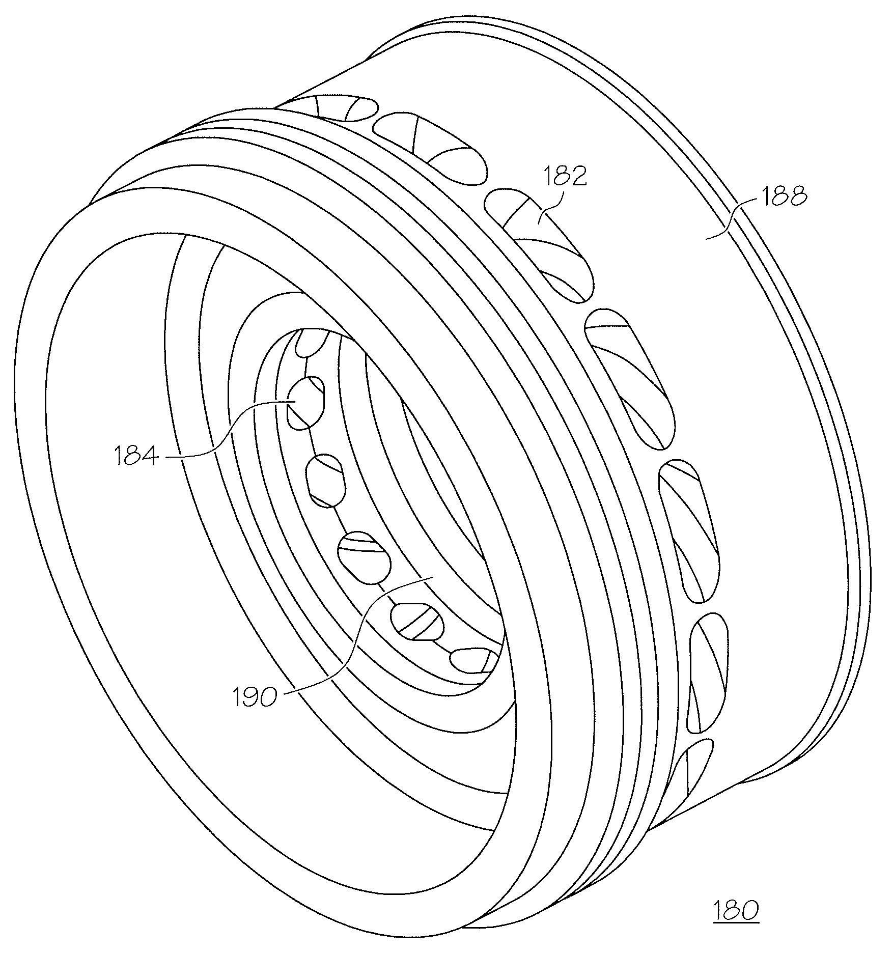
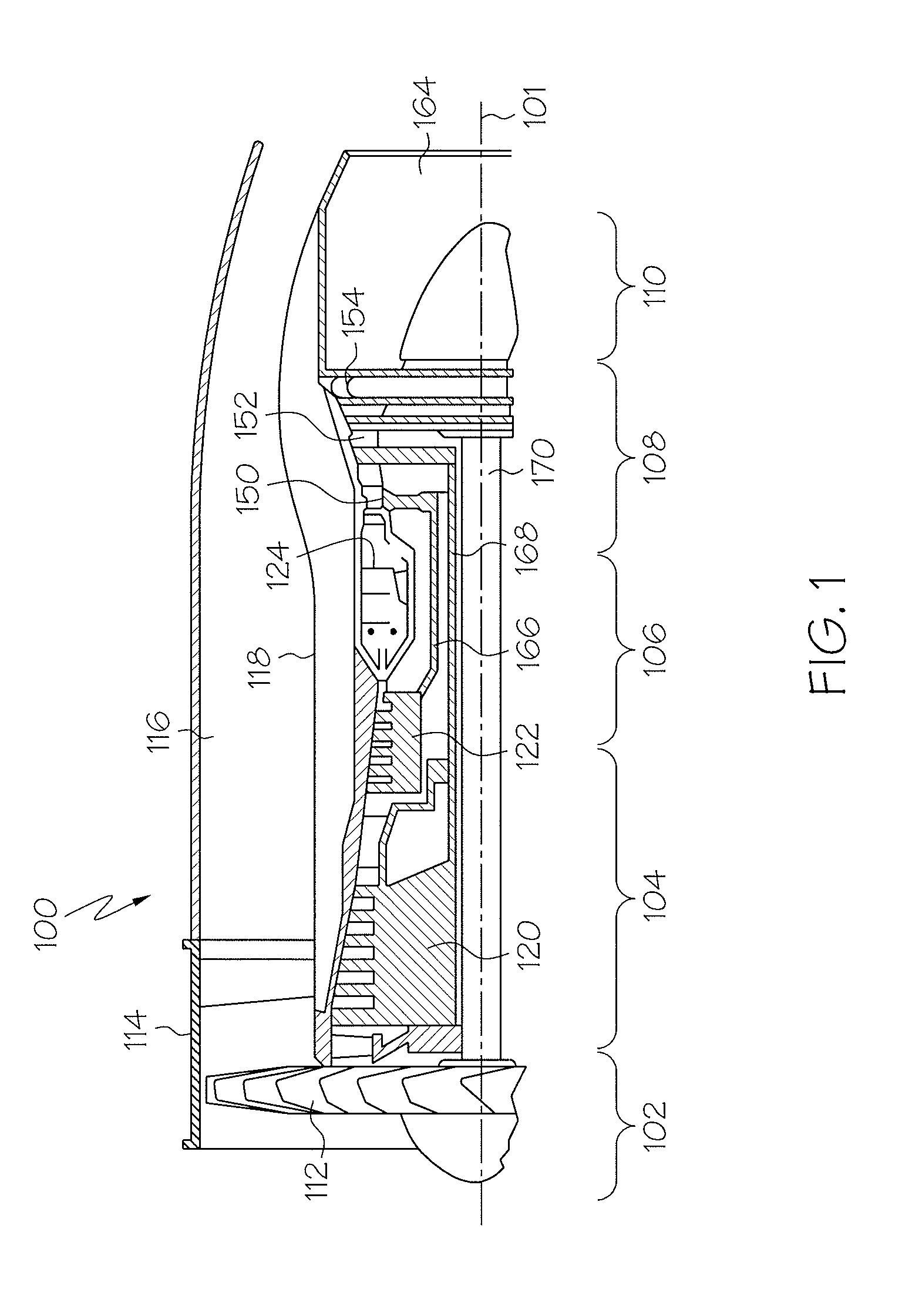
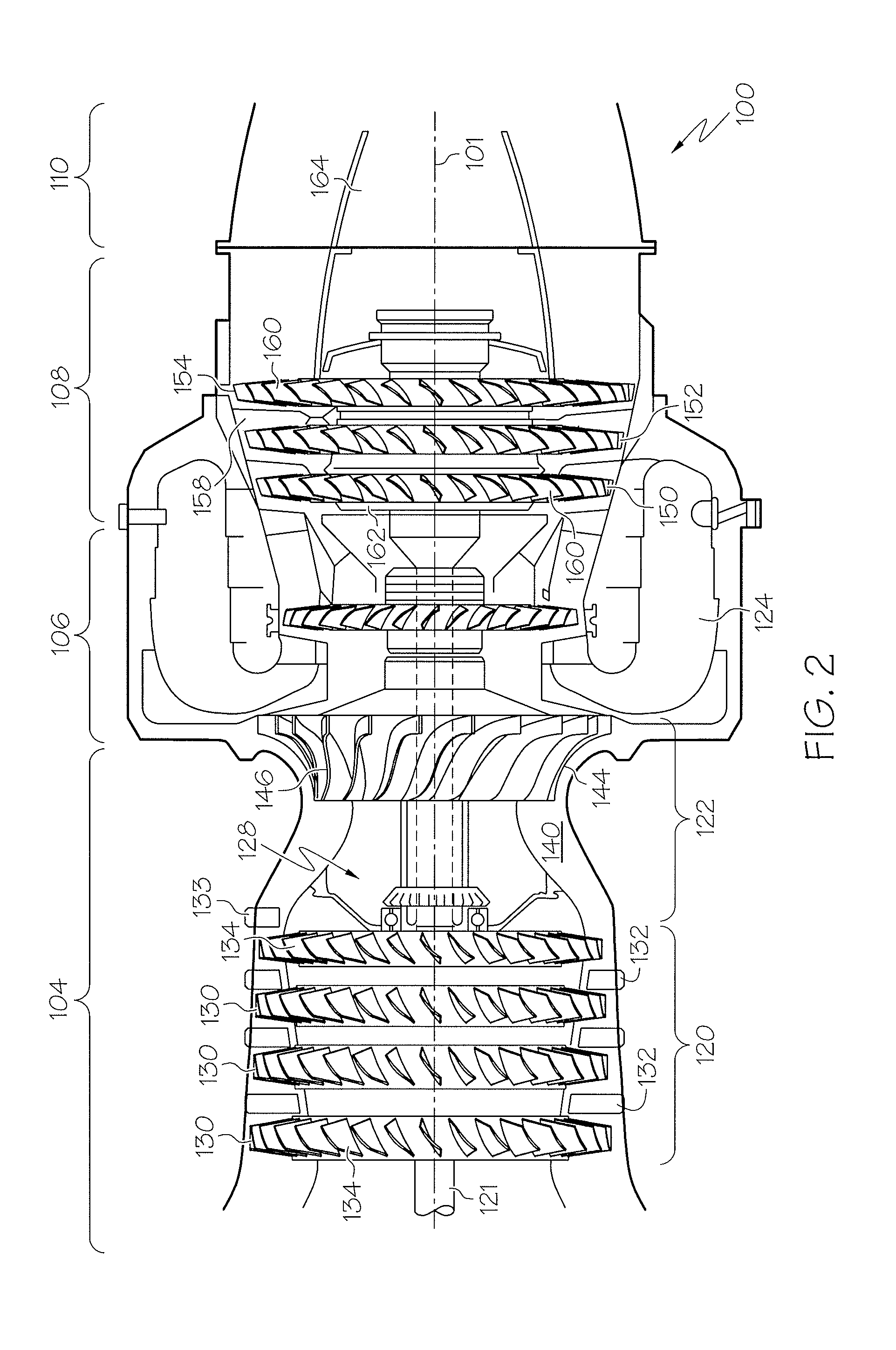
[0023]Referring now to FIGS. 1 and 2, an exemplary embodiment of a turbofan gas turbine jet engine 100 is depicted in FIG. 1 and includes an int...


PUM


Abstract

A vortex spoiler (180) for delivery of a cooling airflow (192) in a turbine (108) engine (100) including a plurality of inlet ports (182) formed circumferentially about a radial exterior sidewall (188), and a plurality of outlet ports (184) formed circumferentially about a radial interior sidewall (190). The plurality of inlet ports (182) are coupled to the plurality of outlet ports (184) via a plurality of ducts (186). Each of the ducts is formed having an interior diameter at the inlet port and the outlet port formed at a preselected angle normal to the surface of the each of the radial sidewalls to form a radially curved profile such that a cooling airflow (192) may pass radially inwardly through each of the plurality of ducts (186) with minimal tangential stress and minimal static pressure loss.

Description

STATEMENT REGARDING FEDERALLY SPONSORED RESEARCH OR DEVELOPMENT[0001]This invention was made with Government support under Contract No. F3361503D2355006 awarded by U.S. Air Force. The Government has certain rights in this invention.TECHNICAL FIELD[0002]The present invention generally relates to turbine engines and more particularly to a vortex spoiler used in the delivery of a cooling airflow to downstream components in the turbine engine.BACKGROUND[0003]Turbine engines are used as the primary power source for many types of aircraft. The engines are also auxiliary power sources that drive air compressors, hydraulic pumps, and industrial gas turbine (IGT) power generation. Further, the power from turbine engines is used for stationary power supplies such as backup electrical generators for hospitals and the like.[0004]Most turbine engines generally follow the same basic power generation procedure. Compressed air generated by axial and / or radial compressors is mixed with fuel and burn...

Claims


Application Information

Patent Timeline
Patent Type & Authority Patents(United States)
IPC IPC(8): F01D5/14
CPCF01D5/081F02C7/18F05D2240/12Y02T50/676F04D29/321Y02T50/60
Inventor MIGNANO, FRANK A.
Owner HONEYWELL INT INC
Why Eureka
Try Eureka