Pressure limiting valve

a technology of pressure limiting valve and valve body, which is applied in the field of valves, can solve the problems of increasing the pressure rise in the system, rising the characteristic curve of the system pressure,

Inactive Publication Date: 2009-07-14
LUK LAMELLEN & KUPPLUNGSBAU BETEILIGUNGS KG
View PDF10 Cites 6 Cited by
  • Summary
  • Abstract
  • Description
  • Claims
  • Application Information

AI Technical Summary

Benefits of technology

[0008]That has the advantage that increasing static pressure losses at the control edges during flow, i.e., so-called flow forces, can be offset by an increasing back pressure on the valve spool, which is produced by the hydraulic resistance.
[0011]That has the advantage that the first control edge opens first, and the influence of flow force occurring there (pressure losses at the spool surface) is offset by the back pressure of the hydraulic resistance. As the volumetric flow increases further, and at the subsequent opening of the second control edge, the volumetric flow over the second control edge will occur with a correspondingly lower pressure difference without additional pressure losses, due to the hydraulic resistance. The pressure losses over the second control edge thus remain low, and a pressure rise of the characteristic curve, as in the case of conventional pressure limiting valves, is thereby reduced.
[0012]A valve in accordance with the invention is distinguished by the fact that the hydraulic resistance is designed in the form of an orifice plate. That has the advantage that temperature influences on the hydraulic medium, which are manifested as changes in the viscosity of the medium, do not significantly influence the pressure drop that occurs at the orifice plate.
[0013]Another valve is distinguished by the fact that the hydraulic resistance is designed in the form of a throttle. That enables temperature influences, and hence viscosity influences, to be used meaningfully for particular effects, if that is desired for the regulating strategy.
[0015]Also preferred is a valve which is pilot-operable by a pilot pressure. A valve is also preferred in which the spool lands have pressure-affected surfaces of varying sizes. That has the advantage that high system pressures, for example, can be regulated with a low pilot pressure.

Problems solved by technology

In such pressure limiting valves, that results in a rising characteristic curve for the system pressure caused by the increasing volumetric flow.
The rise of the pressure characteristic thereby results in an increasing pressure rise in the system, which is actually not wanted.

Method used


Image

  • Pressure limiting valve
  • Pressure limiting valve
  • Pressure limiting valve

Examples


Embodiment Construction

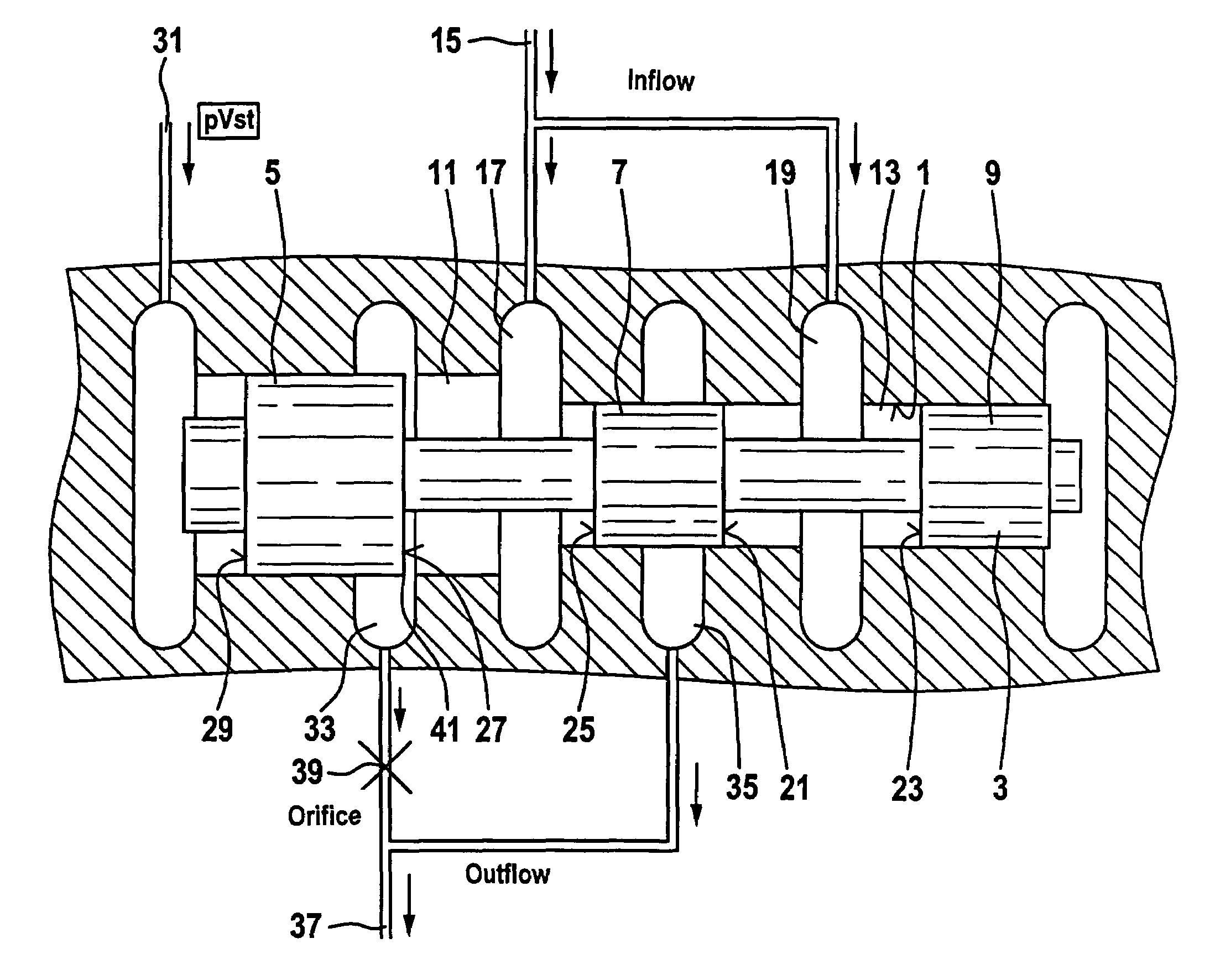
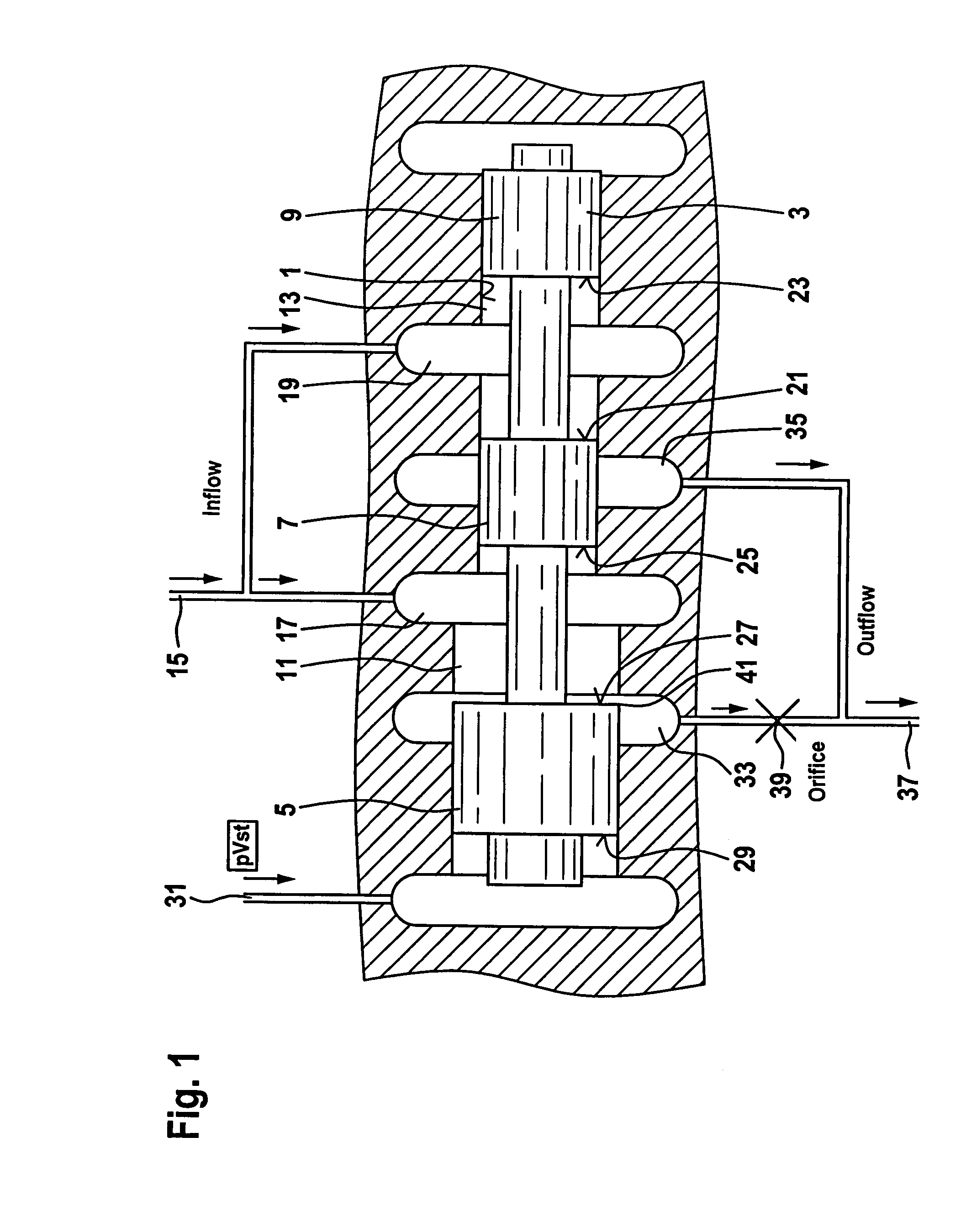
[0023]FIG. 1 shows an embodiment of a pressure-limiting valve in accordance with the invention. A spool 3 having three spool lands 5, 7 and 9 is guided in a spool bore 1. Spool bore 1 has a larger diameter in region 11 than in region 13. Likewise, spool land 5 is larger in diameter than spool lands 7 and 9. Within a valve housing that is not shown directly here, an inflow line 15 is divided into a first infeed chamber 17 and a second infeed chamber 19, each in the form of circumferential grooves. When system pressure is present in inflow line 15, the forces of the system pressure acting on pressure-affected surface 21 of spool land 7 and on pressure-affected surface 23 of spool land 9 will cancel each other out. The system pressure in infeed chamber 17, which acts on the smaller area pressure-affected surface 25 of spool land 7 and on the larger area pressure-affected surface 27 of spool land 5, produces a pressure differential force in the valve opening direction. That opening forc...


PUM


Abstract

A pressure limiting valve having a spool with raised spool lands. The spool is slidably received in a spool bore having inflow and outflow grooves that form control edges. The valve has two control edges, and a hydraulic resistance is connected in series with one of the control edges. Increasing static pressure losses at the control edges during flow, so-called flow forces, can be offset by an increasing back pressure on the valve spool, which is produced by the hydraulic resistance.

Description

CROSS-REFERENCE TO RELATED APPLICATION[0001]This is a continuation of International Application Ser. No. PCT / DE2005 / 001844, with an international filing date of 15 Oct. 2005, and designating the United States, the entire contents of which is hereby incorporated by reference to the same extent as if fully rewritten.BACKGROUND OF THE INVENTION[0002]1. Field of the Invention[0003]The present invention relates to a valve, in particular a pressure limiting valve having a spool with spool lands, which form control edges with inflow and outflow grooves in a spool bore / guide.[0004]2. Description of the Related Art[0005]Such valves are known. The valve has, for example, a spool land that is subjected on one side to a pilot pressure and on the other side to a pressure of a main hydraulic system. If the pressure force of the system pressure exceeds the pressure force of the pilot pressure, then the spool begins to move and allows an opening to form at a groove, whereby a flow arises at the con...

Claims


Application Information

Patent Timeline
Patent Type & Authority Patents(United States)
IPC IPC(8): G05D11/00
CPCF16D48/02F16K17/046F16D2048/0209Y10T137/2562
Inventor MULLER, ERICHOMM, MANFREDSTEHR, REINHARD
Owner LUK LAMELLEN & KUPPLUNGSBAU BETEILIGUNGS KG
Why Eureka
Try Eureka