Sea survival device including several pneumatic liferafts

a liferaft and sea survival technology, applied in life-saving, vessel safety, pontoons, etc., can solve the problems of not being structurally and functionally designed to be deployed from a ship carrying passengers (liner, ferry, etc.) or from an offshore platform, so as to reduce the amount of space needed, less voluminous, and less heavy

Active Publication Date: 2010-05-04
SURVITEC
View PDF7 Cites 5 Cited by
  • Summary
  • Abstract
  • Description
  • Claims
  • Application Information

AI Technical Summary

Benefits of technology

[0013]By means of these features, each liferaft is inflated separately, and can be deployed without being hindered by another liferaft, which is essential for operationally deploying liferafts of very high capacity and thus of very large dimensions. In addition, it is essential for the liferafts to be deployed individually when they are self-righting liferafts, whose self-righting capacity can be guaranteed only if nothing hinders them as they are righting in the event that they are inflated upside-down.
[0016]It is also possible for a tie to be provided between the successive liferafts in a manner such that, while a liferaft is being inflated, the remaining portion of the container enclosing the other liferafts remains secured to the liferaft that is being inflated. Naturally, the tie is flexible and is of a length that is sufficient for the floating remaining portion of the container not to be swept too far away while the first liferaft is being deployed, but also for it not to hinder deployment of that preceding liferaft.
[0017]The features that are descried above can apply as they are to sets of several liferafts, which makes it possible to reduce the amount of space necessary on the deck of the ship for stowing the container enclosing the liferafts (for the same liferaft capacity, such a common container is significantly less voluminous and less heavy than several containers each enclosing a single liferaft).
[0018]However, the features of the invention would seem to find a particularly advantageous application in the context of high-capacity and high-speed evacuation systems with which large ships for carrying passengers (liners, ferries, etc.) are currently or soon to be provided. It is, in particular, in this context that it is possible to make provision for the first liferaft of the present invention to be a boarding platform, at least a portion of which is arranged as a zone for receiving evacuees, in particular by means of rapid evacuation means. An example of such a boarding platform with a reception zone is given in document FR 2 756 809. Also in this context, it is then possible to make provision for the survival device to further comprise an inflatable pneumatic slide that, when the device is in the stowed condition, is folded up and rolled up around the container from its entry end which is secured to the container. Advantageously, the device can further comprise fastening means that, in the in-use position, are suitable for securing the exit end of the slide to the first liferaft in register with the reception zone provided therein. Also in the same context, it is possible for tie means to be provided for securing the first liferaft to each of the other liferafts with their sides touching once they are deployed (optionally one after another) in a manner such as to make it easier for people to go from one liferaft to another, in particular from the boarding platform to the liferaft proper. The features that are described above can find a particularly advantageous application for liferafts of very high capacity (typically several tens of people, or indeed more than about one hundred people) that are starting to equip ships for carrying passengers (cruise liners or other liners, car ferries, etc.).

Problems solved by technology

However, simultaneously deploying the two liferafts is possible only when they are relatively small in size.
Such a device is specifically arranged for aircraft rescue of survivors in water, but it is not structurally and functionally designed to be deployed from a ship carrying passengers (liner, ferry, etc.) or from an offshore platform, in order to enable a large number of people to survive at sea.

Method used


Image

  • Sea survival device including several pneumatic liferafts
  • Sea survival device including several pneumatic liferafts
  • Sea survival device including several pneumatic liferafts

Examples


Embodiment Construction

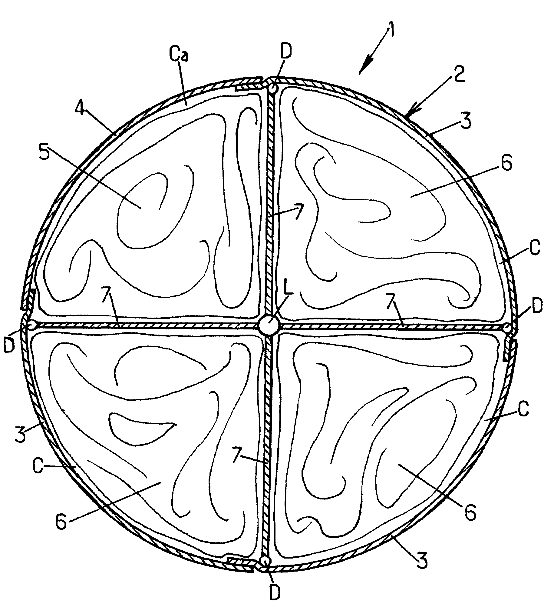
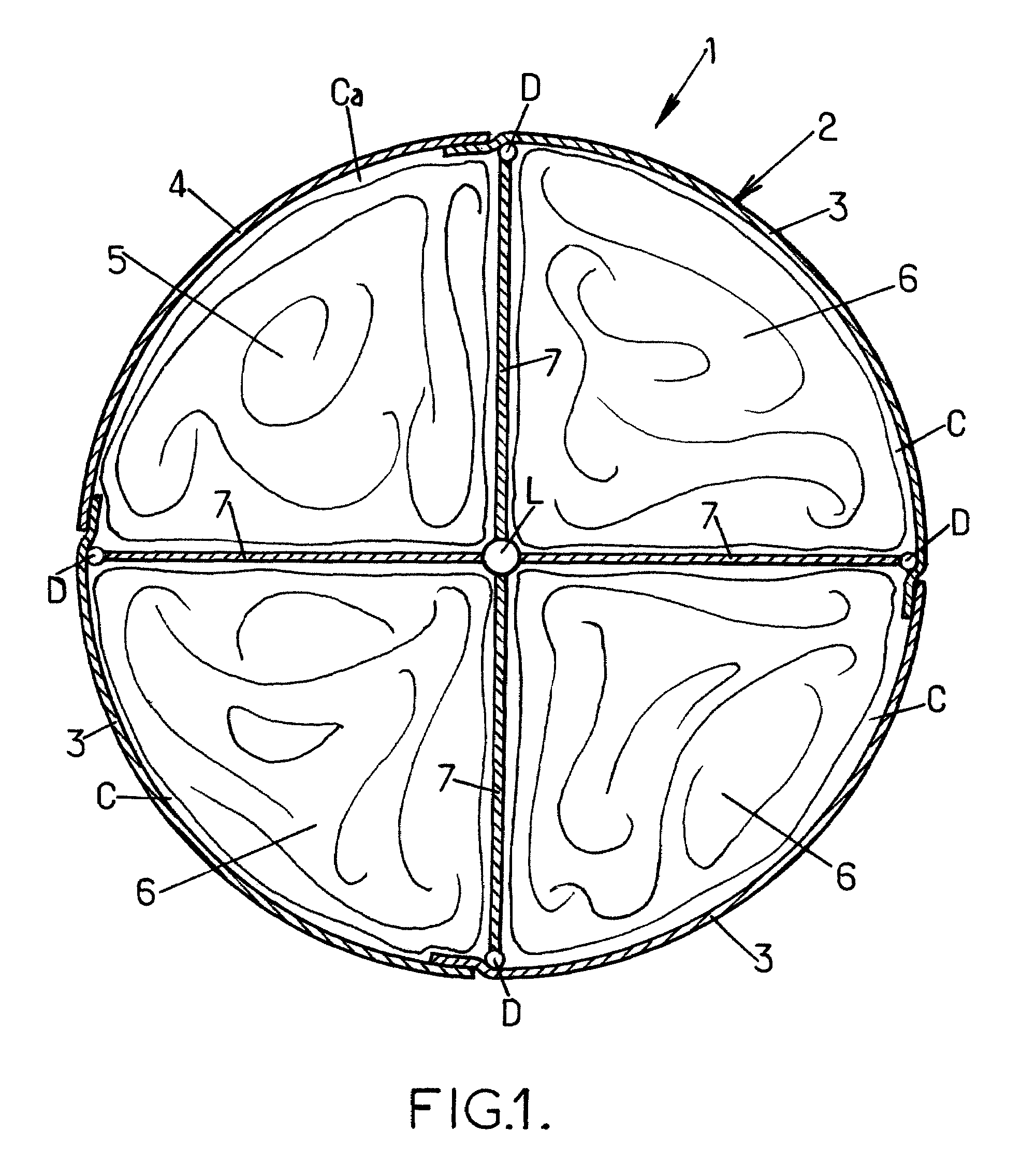
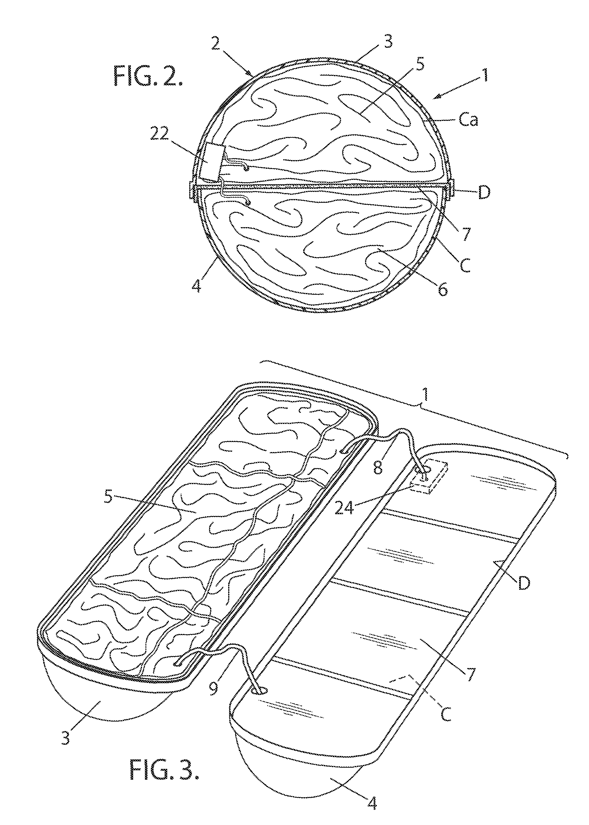
[0037]Reference is made firstly to FIG. 1 which is a highly diagrammatic view of a sea survival device that is designated by overall numerical reference 1, and that comprises a container 2 enclosing several pneumatic liferafts in the deflated and folded-up state together with suitable inflation means for inflating said liferafts. In accordance with the invention, the sea survival device 1 is arranged as explained below.

[0038]The container 2 is made up of several assembled-together rigid shells 4, one of which is a special shell 3 that is described below. The shells 3, 4 can be made of any suitable material used for manufacturing containers designed to enclose liferafts, and the shells are shaped in a manner such that the container 2 has any desired shape that is appropriate for performing its function; the shells 3, 4 are mechanically assembled together in a manner such as to impart the required strength to the container, in particular if it is designed to be thrown into the water f...


PUM


Abstract

A sea survival device (1) comprising a container (2) with several shells (3, 4) enclosing respective pneumatic liferafts (5, 6) in the deflated and folded-up state, and inflation means; one half-shell (4) enclosing a liferaft (6) is closed by a closure partition (7); the automatically triggered inflation means are operationally associated with at least the first liferaft (5) in a manner such that said first liferaft (5) is inflated first when the survival device (1) is deployed operationally; and the liferaft (6) is operationally associated with inflation trigger means suitable for trigging inflation thereof only once the first liferaft (5) is inflated.

Description

CROSS-REFERENCED TO RELATED APPLICATION[0001]This application claims the benefit of French Patent Application No. FR 07 00749 filed with the French Patent Office on Feb. 2, 2007, the contents of which are incorporated herein by reference.FIELD OF THE INVENTION[0002]The present invention relates in general to the field of survival at sea and, more specifically, it relates to improvements made to a sea survival device comprising a container that encloses several pneumatic liferafts in the deflated and folded-up state, together with inflation means for inflating said liferafts while the device is being deployed operationally.DESCRIPTION OF THE PRIOR ART[0003]Sea survival devices of the above-mentioned type are already known, with two pneumatic liferafts enclosed in a common container.[0004]Thus, document U.S. Pat. No. 4,362,517 discloses a set of two pneumatic liferafts housed, in the deflated and folded-up state, in a common rigid container, together with common inflation means. On in...

Claims


Application Information

Patent Timeline
Patent Type & Authority Patents(United States)
IPC IPC(8): B63B35/38
CPCB63C9/02B63C9/22B63C9/04B63C2009/042
Inventor SIMON-BOUHET, GUILLAUME
Owner SURVITEC
Why Eureka
Try Eureka