Apparatus and method for cutting elastic strands between layers of carrier webs

a carrier web and elastic strand technology, applied in the field of apparatus and method for cutting elastic strands between carrier web layers, can solve problems such as potential loss of elasticity, and achieve the effect of retaining its shape and flexibility

Inactive Publication Date: 2010-05-04
CURT G JOA
View PDF442 Cites 109 Cited by
  • Summary
  • Abstract
  • Description
  • Claims
  • Application Information

AI Technical Summary

Benefits of technology

[0008]Once the fabric layers are sealed together into a single web, the single web may be folded and bonded to form a diaper. Typically a diaper is bonded using a thermal or ultrasonic method. When this occurs, the inner elastic material will be melted and severed at the point of the bond. Normally this results in potential loss of elasticity as elastic strands may come loose or snap back when severed. However, the present invention allows the elastic material to retain its shape, even after severing.
[0009]The present invention also allows quicker and easier placement of the elastic material within the webs of material. Not every area within an undergarment is desired to be elastic. The present method allows the use of heat compression to remove specific areas of elastic material after being placed between the two webs of fabric. For instance, in certain applications, elastic material is generally not necessary or wanted below the waistline of a diaper wearer. The areas where the webs of fabric are to be bonded do not need elastic material present, either. By using heat that severs and melts the elastic while retaining the required elasticity, the present method allows for the possibility to form such non-elastic areas after the webs of fabric are sealed together.

Problems solved by technology

Normally this results in potential loss of elasticity as elastic strands may come loose or snap back when severed.

Method used


Image

  • Apparatus and method for cutting elastic strands between layers of carrier webs
  • Apparatus and method for cutting elastic strands between layers of carrier webs
  • Apparatus and method for cutting elastic strands between layers of carrier webs

Examples


Embodiment Construction

[0020]Although the disclosure hereof is detailed and exact to enable those skilled in the art to practice the invention, the physical embodiments herein disclosed merely exemplify the invention that may be embodied in other specific structure. While the preferred embodiment has been described, the details may be changed without departing from the invention.

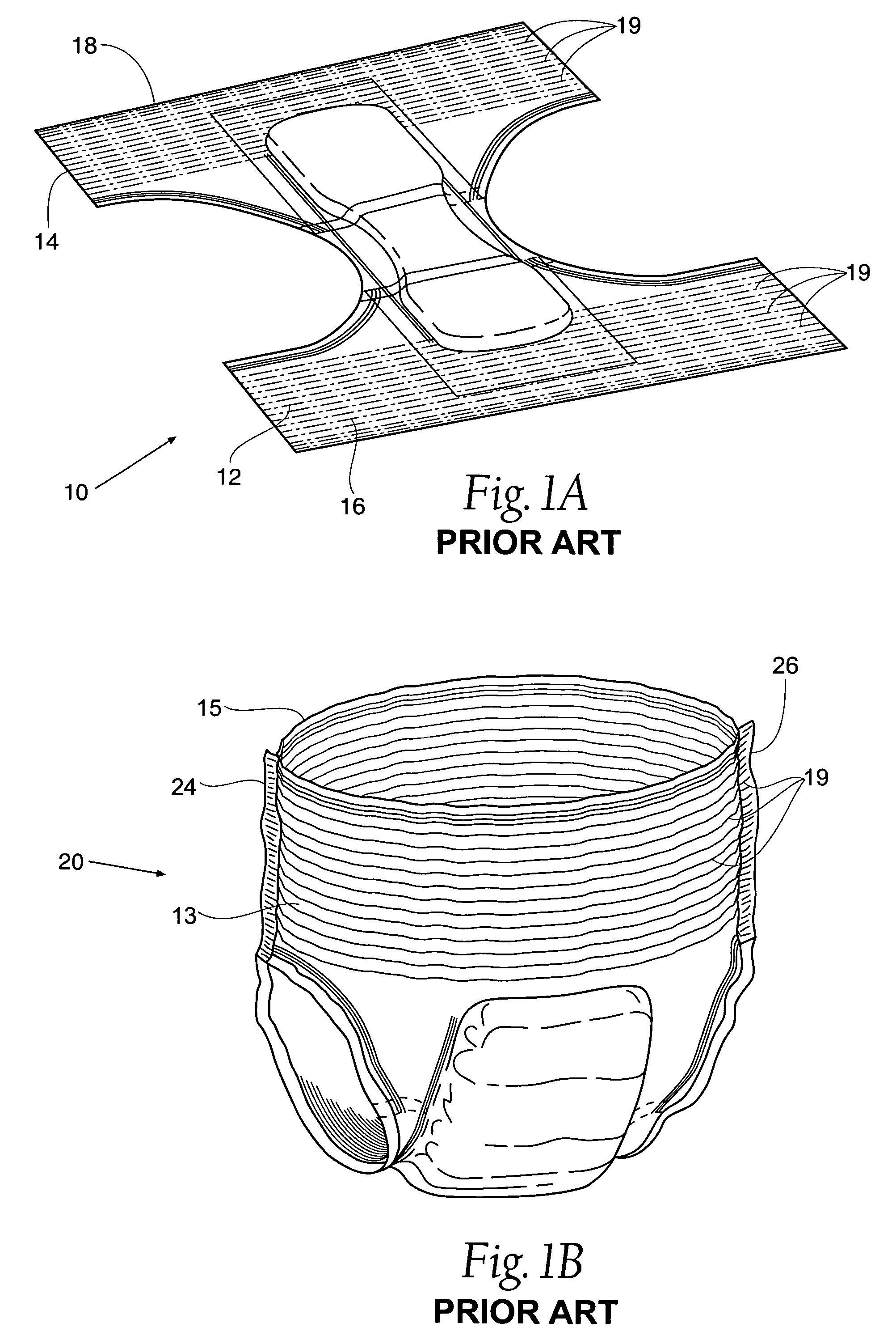
[0021]FIG. 1A shows a perspective view of a prior art undergarment blank 10. The blank 10 is of a symmetrical design having a first half 12 and a second half 14. As shown in FIG. 1B, the first half 12 will form a front portion 13 of an undergarment 20 and the second half 14 will form a back portion 15 of the undergarment 20. Elastic sections 16 and 18 are located within the first half 12 and the second half 14, respectively. The elastic sections 16 and 18 are made up of a plurality of individual elastic strands 19. Such a design allows for the specific designated areas of the undergarment 20 to have elastic properties instead of t...


PUM

PropertyMeasurementUnit
elasticaaaaaaaaaa
tensionaaaaaaaaaa
areaaaaaaaaaaa

Abstract

A method of utilizing a scrim of elastic material including cutting the elastic strands within a disposable undergarment is disclosed. The method generally follows the steps of providing two webs of fabric and an elastic scrim of mesh-like design, adhering the scrim between the two webs of fabric, determining areas where elastic material is not required, compressing the non-elastic areas with a thermal compression tool, and forming a disposable undergarment.

Description

RELATED APPLICATION[0001]This application is a continuation-in-part of application U.S. Ser. No. 10 / 828,095, filed 20 Apr. 2004, now abandoned.BACKGROUND OF THE INVENTION[0002]Disposable diapers of the children's training pant type, or of the adult incontinence type, are typically equipped with elastic strands, which generally encircle the waistband area and leg-holes. These strands of elastic are typically captured with adhesive between two layers of nonwoven materials. Various methods are used to position these elastic strands so that they produce the desired effect in the desired areas.[0003]Several methods of cutting elastic strands in diaper manufacturing exist. One method of cutting the strands is to sever them ultrasonically, as described in U.S. Pat. No. 5,660,657. As taught in U.S. Pat. No. 5,707,470, an ultrasonic device can be used to sever elastic members, while the carrier webs that encapsulate the elastics are left intact.[0004]One problem associated with prior art sev...

Claims


Application Information

Patent Timeline
Patent Type & Authority Patents(United States)
IPC IPC(8): B32B37/00A61F13/15B26D7/26B26F1/20
CPCA61F13/15593A61F13/15723A61F13/15739B26F1/20D04H1/559D04H13/00D04H1/593B26D7/2628Y10T156/1052Y10T156/1084Y10T156/108Y10T156/1015Y10T156/1062
Inventor MCCABE, JOHN A.
Owner CURT G JOA
Why Eureka
Try Eureka