Bridged LAN and communication node therefor
a communication node and bridge technology, applied in the field of bridged lan, can solve the problems of difficult to construct a different spanning tree for each of the services in the transit network, and achieve the effect of high real-time property
- Summary
- Abstract
- Description
- Claims
- Application Information
AI Technical Summary
Benefits of technology
Problems solved by technology
Method used
Image
Examples
embodiment 1
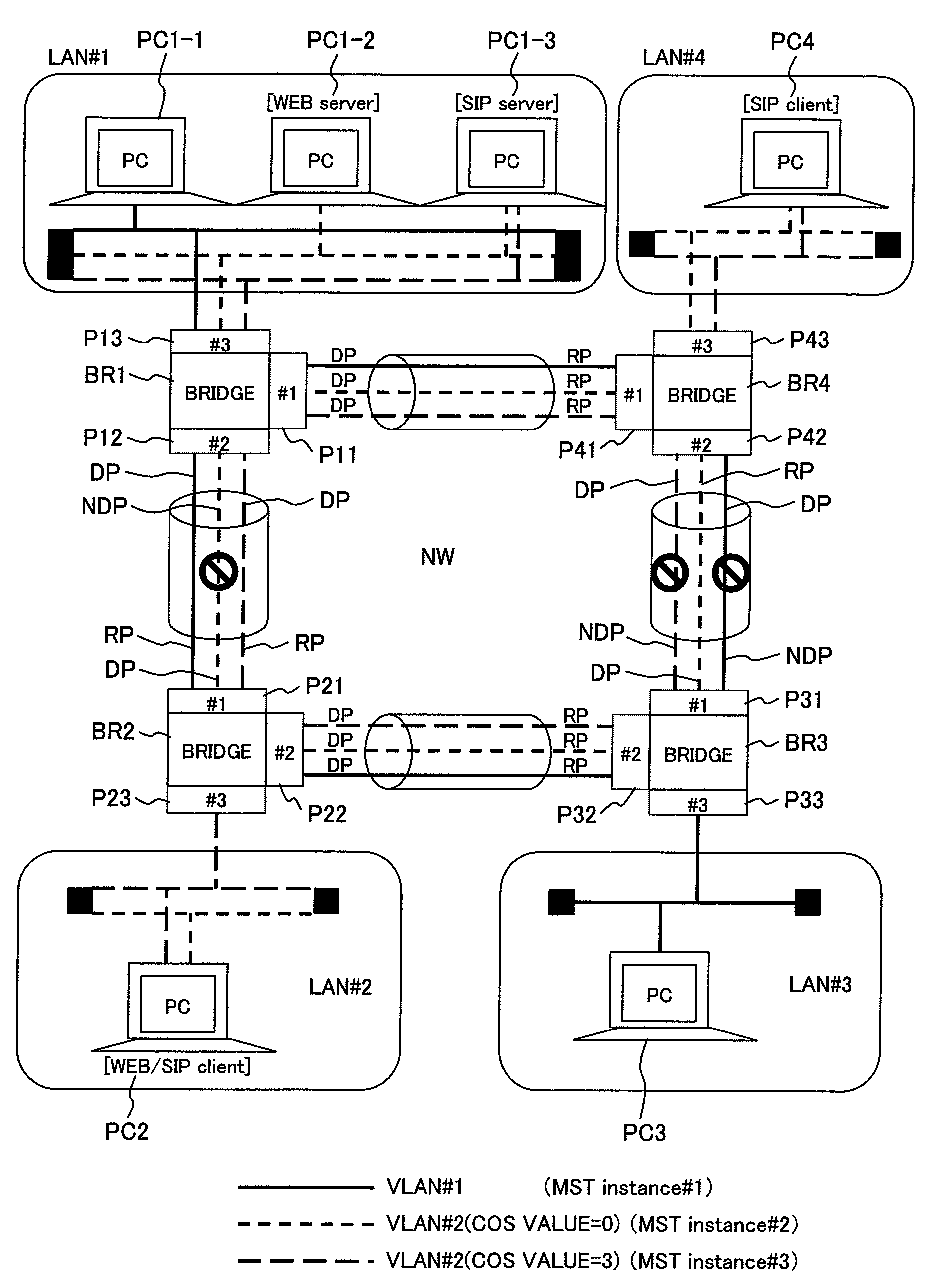
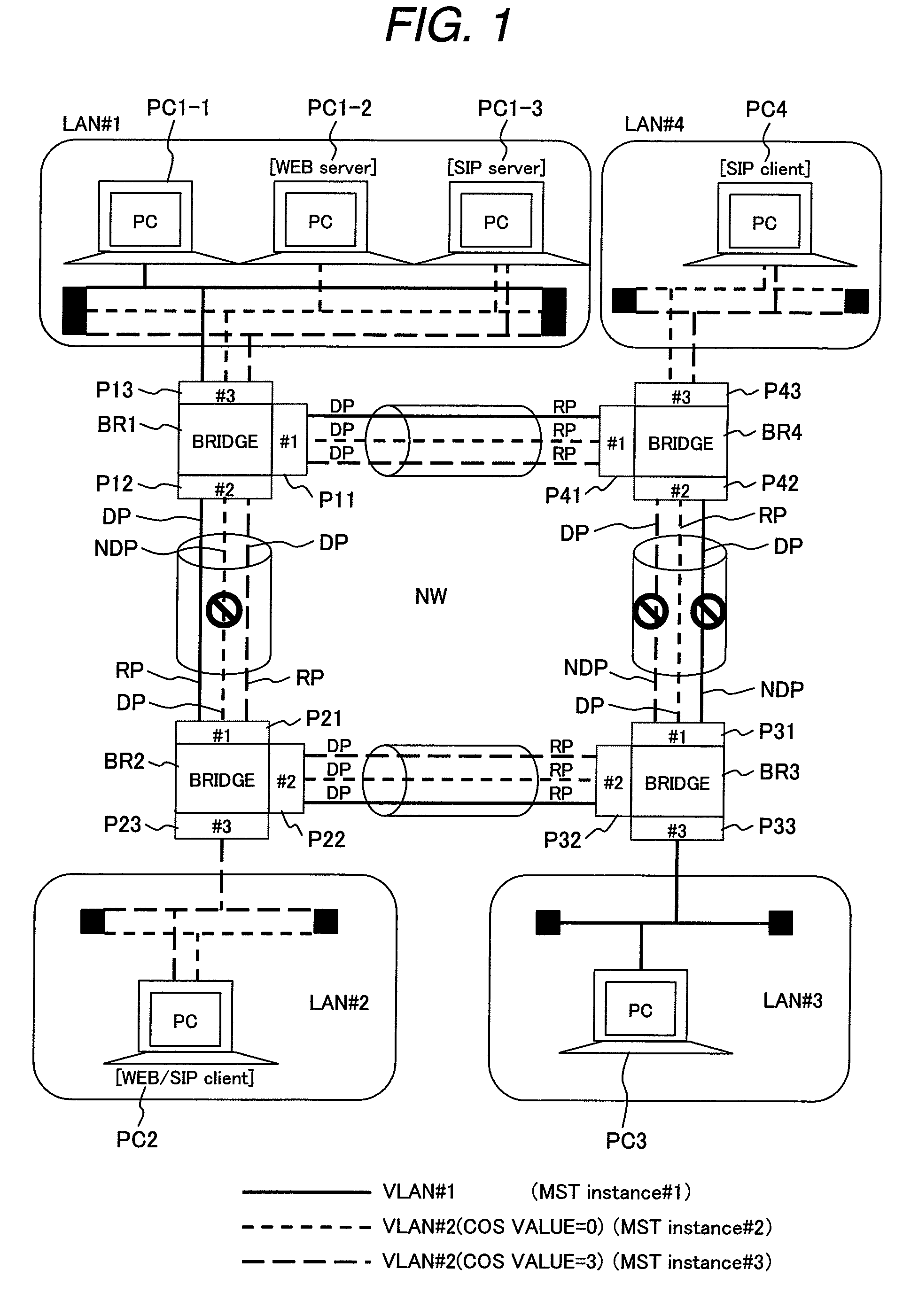
[0061]FIG. 1 shows an example of a network structure of a bridged VLAN to which the present invention is applied. The network shown here as an example includes LANs #1 to #4 and a transit network NW including bridges BR1 to BR4 connected in a loop-like shape. To the LANs #1 to #4, personal computers PC1-1 to PC1-3, PC2, PC3, and PC4 are connected, respectively, in the same manner as in FIG. 20.
[0062]In the bridged LAN shown in FIG. 1, two VLANS; a VLAN #1 indicated by the solid line and a VLAN #2 indicated by the broken line, are formed. In the same manner as in FIG. 20, the personal computer PC1-1 connected to the LAN #1 and the entire LAN #3 belong to the VLAN #1. The personal computers PC1-2 and P1-3 each connected to the LAN #1, the entire LAN #2, and the entire LAN #4 belong to the VLAN #2. In the VLAN #2, the personal computer PC1-2 functions as a WEB server, the personal computer PC1-3 functions as a SIP server, the personal computer PC2 is a client of WEB and SIP, and the pe...
embodiment 2
[0100]FIG. 12 shows an example of a structure of another network structure of the bridged VLAN to which the present invention is applied.
[0101]The network shown in FIG. 12 is different from that of FIG. 1 in that another LAN #5 is connected to the transit network NW via a gateway GW1. Although the gateway GW1 is connected to the transit network NW via the LAN #2 in FIG. 12, the gateway GW1 may be connected directly to the Ethernet port P23 of the bridge BR2.
[0102]The gateway GW1 is connected to the LAN #2 via an Ethernet port GP1 and connected to the LAN #5 via an Ethernet port GP2 to forward communication frames received from the LAN #5 to the LAN #2 and forward communication frames received from the LAN #2 to the LAN #5.
[0103]Upon receiving a communication frame from the LAN #5, the gateway GW1 according to the present embodiment specifies the COS value in accordance with the TCP / UDP port number indicated by the received frame, sets the specified COS value to the tag field of the ...
PUM
 Abstract
Description
Claims
Application Information
 - R&D
- Intellectual Property
- Life Sciences
- Materials
- Tech Scout
- Unparalleled Data Quality
- Higher Quality Content
- 60% Fewer Hallucinations
Browse by: Latest US Patents, China's latest patents, Technical Efficacy Thesaurus, Application Domain, Technology Topic, Popular Technical Reports.
© 2025 PatSnap. All rights reserved.Legal|Privacy policy|Modern Slavery Act Transparency Statement|Sitemap|About US| Contact US: help@patsnap.com


