Connecting device and process for the manufacture of ducts for heating, conditioning, and ventilation

a technology of connecting device and duct, which is applied in the direction of duct connection, hose connection, duct arrangement, etc., can solve the problems of affecting the overall cost of manufacturing said duct, affecting the building process, and becoming much longer, so as to reduce the operating time, reduce the cost of connection, and reduce the effect of cos

Active Publication Date: 2010-05-11
KINGSPAN HLDG (IRL) LTD
View PDF12 Cites 26 Cited by
  • Summary
  • Abstract
  • Description
  • Claims
  • Application Information

AI Technical Summary

Benefits of technology

[0012]Within the scope of this technical task it is an important aim of the invention to conceive a connecting device and process for manufacturing ducts that is capable of greatly reducing the operating time required while making it exactly foreseeable, which will bring about a reduction in the costs connected with manpower.
[0013]Another important aim of the invention is to conceive a connecting device of reduced cost so that, as a result, the overall costs of the materials used in manufacturing said ducts will be ultimately reduced.
[0014]A still further aim is to conceive a connecting device and process simplifying and making easier the operating steps for manufacturing said ducts while avoiding creation of noxious and dangerous environmental situations.

Problems solved by technology

This period of time varies depending on the temperature and humidity and can become much longer under particular unfavorable weather conditions.
In fact, first of all, it contemplates a stop in the duct building process for a period of time that is sometimes rather long and often cannot be exactly foreseen, due to the fact the glue drying time is not always the same.
In addition, the special glues used to obtain a steady and safe union of the duct sides are very expensive and therefore greatly affect the overall costs for manufacturing said ducts.
Finally, it is to be pointed out that the operations for glue application and assembling of the glue-coated parts are characterized by a non negligible complexity of execution and all expedients, measures and safety precautions prescribed by the regulations in force are required to be complied with because the glue may contain inflammable or toxic components.

Method used


Image

  • Connecting device and process for the manufacture of ducts for heating, conditioning, and ventilation
  • Connecting device and process for the manufacture of ducts for heating, conditioning, and ventilation
  • Connecting device and process for the manufacture of ducts for heating, conditioning, and ventilation

Examples


first embodiment

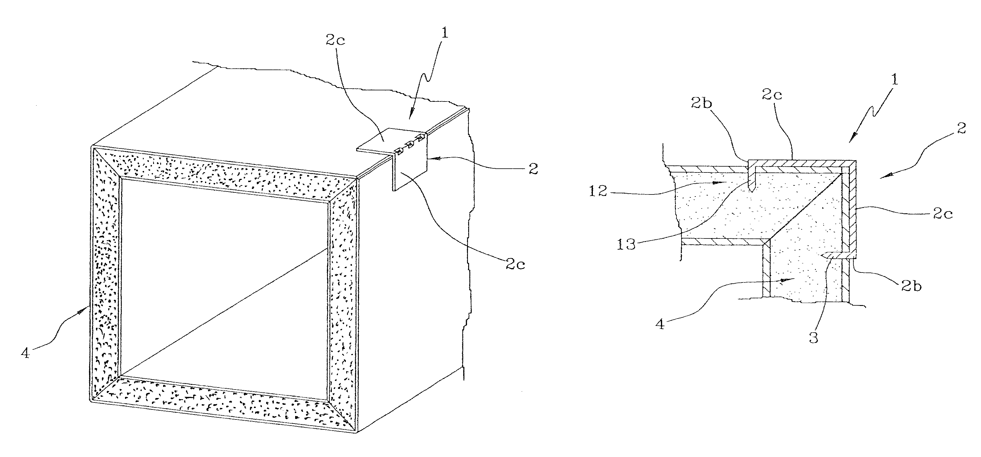
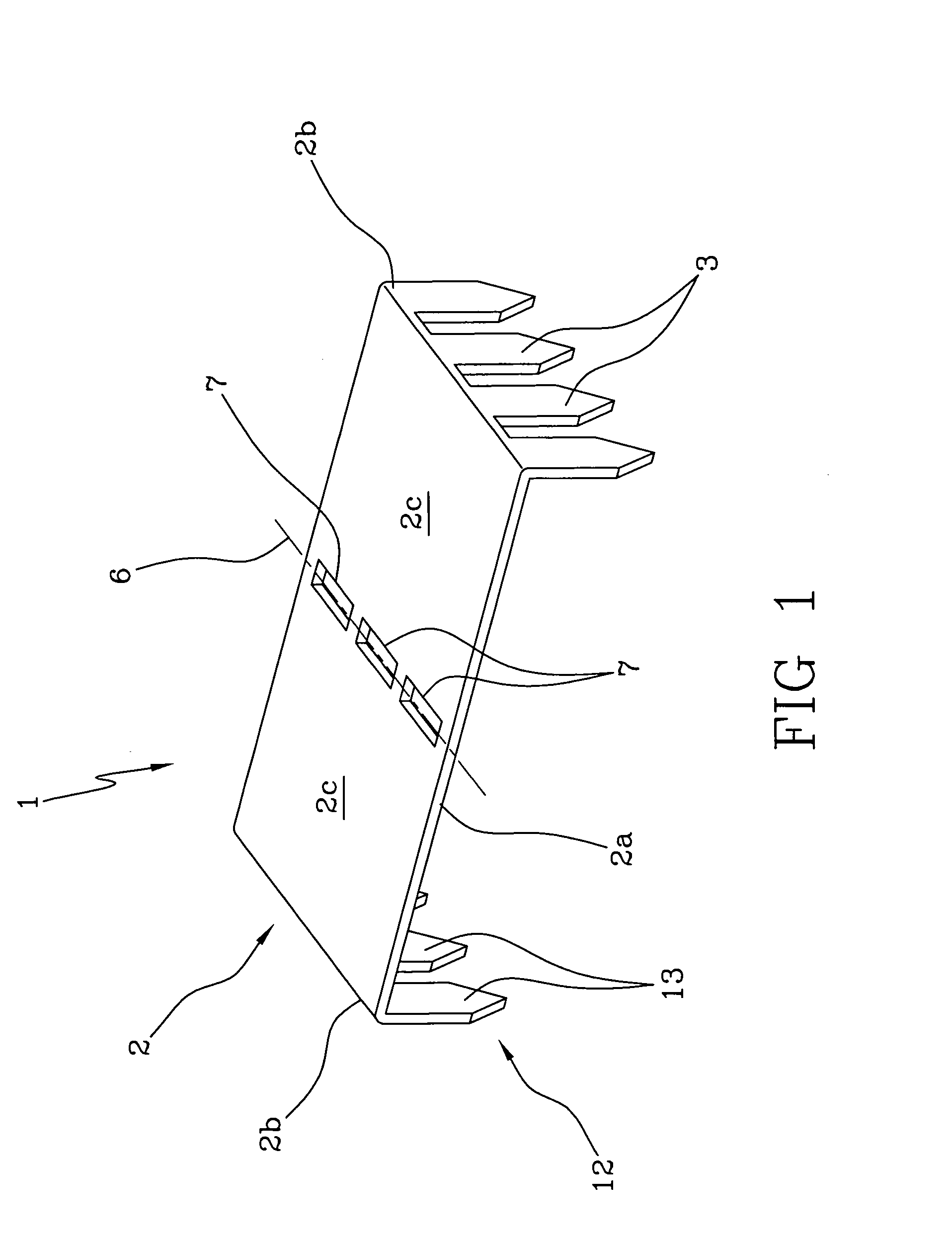
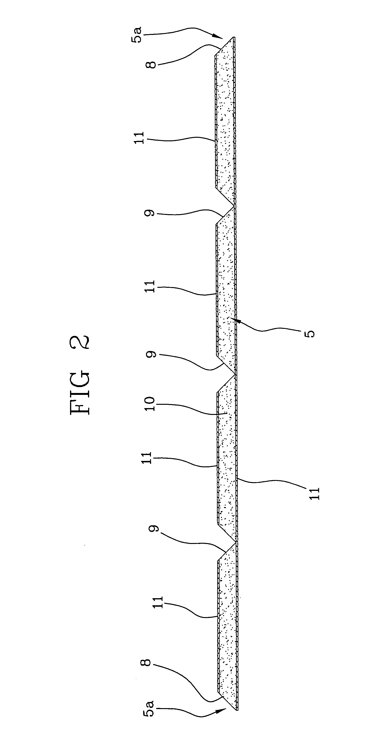
[0028]Looking now at FIGS. 1 to 5, the device, in its first embodiment, comprises a plate-like element 2 having at least two hooking points 3, 13 on a face 2a thereof, four hooking points for each of the opposite edges 2b of the same plate-like element 2, for example. The hooking points 3 and 13 project from face 2a in a direction substantially perpendicular and have a tooth-shaped conformation adapted to penetrate contiguous portions to be joined of a single duct segment 4 (as in the example in FIG. 3) or of two consecutive duct segments 4 (as in the example in FIG. 5) for example, advantageously formed from panels 5 consisting of an insulating material 10 sandwiched between two preferably metallic thin sheets 11. In one embodiment, use of an insulating material 10 consisting of phenolic foam coated with aluminum on both sides is provided.

[0029]The plate-like element 2 further has a weakening region or strip 6 interposed between the hooking points 3, 13 and adapted to define a bend...

second embodiment

[0039]Vice versa, looking at the second embodiment shown in FIGS. 6 to 9, it is possible to see that the plate-like element 2 in addition to having the already mentioned hooking points 3 is provided at one end thereof, at the opposite side 2b, with a predetermined number of holes 14 for fastening of a duct accessory 15 such as a fan coil (FIG. 9) or an air lock (FIG. 8), by means of screws, rivets or similar junction devices for example.

[0040]In particular, the plate-like element will not only be provided with the weakening strip 6 formed with the respective slits 7, but also with a second weakening strip 16 adapted to define a second bending line of the plate-like element itself to enable the latter to be divided into three angled flat portions 2c (in this connection see FIGS. 7a and 7b).

[0041]The second weakening strip 16 too is made up of a plurality of through slits 17 possibly of a shape and configuration different from the preceding ones, which are however mutually aligned.

[00...


PUM

PropertyMeasurementUnit
angleaaaaaaaaaa
thicknessaaaaaaaaaa
bendingaaaaaaaaaa

Abstract

It is disclosed a connecting device for the manufacture of ducts for heating, conditioning, ventilation comprising a plate-like element (2) which is provided, on a face (2a) thereof at opposite positions, with at least two hooking points (3) adapted to penetrate contiguous portions to be joined of a duct (4) segment or of two consecutive duct segments. Also provided is a connecting process comprising a step of applying at least one connecting device (19 on either side of a junction line (4a) defined by two opposite longitudinal bands of a panel (5) adapted to form a duct (4) segment.

Description

FIELD AND BACKGROUND OF THE INVENTION[0001]The present invention relates to a connecting device and process for the manufacture of ducts for heating, conditioning, ventilation and similar applications.[0002]It is known that a great number of types of conditioning / heating ducts are present on the market which differentiate from each other in terms of manufacturing methods, materials, sizes and assembling and hooking systems. Among these types there is one contemplating manufacture of ducts of suitable section starting from flat sandwich panels consisting of a core of insulating material interposed between two thin metal sheets.[0003]Manufacture of ducts for the above mentioned applications is carried out following a sequence of operating steps comprising a starting step of suitably arranging the panels of insulating material cut to size to form the different segments of the expected ducts.[0004]In particular, in the case of straight ducts of a rectangular section and consisting of a ...

Claims


Application Information

Patent Timeline
Patent Type & Authority Patents(United States)
IPC IPC(8): F16L11/12
CPCF16B15/0046F16L9/003F24F13/02Y10T403/553Y10T403/55
Inventor VINCENTI, GIOVANNI
Owner KINGSPAN HLDG (IRL) LTD
Why Eureka
Try Eureka