
Image forming apparatus and image forming method

a technology of image forming apparatus and forming method, which is applied in the field of image forming apparatus and image forming method, can solve the problems of displaced coloring materials, no solvent can be used, and difficult to print images on a large number of sheets at high speed by means of a direct recording method, so as to prevent image disturbance, generate wasteful expendable materials, and high versatility

Inactive Publication Date: 2010-05-11
FUJIFILM CORP
View PDF8 Cites 43 Cited by
  • Summary
  • Abstract
  • Description
  • Claims
  • Application Information

AI Technical Summary

Benefits of technology

The solution effectively prevents image disturbance during transfer, allows for the use of various liquid types, and eliminates wasteful expendable materials, providing high versatility in recording media, while ensuring reliable provisional fixing of the solvent-insoluble material on the intermediate transfer body.

Problems solved by technology

An inkjet recording apparatus is provided with an inkjet head (which is hereinafter simply referred to as a “head”) having an ink ejection part including nozzles manufactured by using a high-precision processing technique, still it is difficult to print images on a large number of sheets at high speed by means of a direct recording method known in the related art, under the ejection conditions that have become extremely.
However, this essentially utilizes the electrophoresis, then no solvent can be used other than the oil-based solvent having high insulating properties.
Here, the coloring material is not fixed on the intermediate transfer body even provisionally, and hence there is a possibility that the coloring material is displaced and the image disturbance occurs, when transferring the coloring material to the recording medium.
In this inkjet recording apparatus, the coloring material is aggregated before removing the solvent, but not fixed on the intermediate transfer body even provisionally, and the image disturbance may occur when the solvent is removed.

Method used


Image

  • Image forming apparatus and image forming method
  • Image forming apparatus and image forming method
  • Image forming apparatus and image forming method

Examples


Embodiment Construction

Composition of Inkjet Recording Apparatus

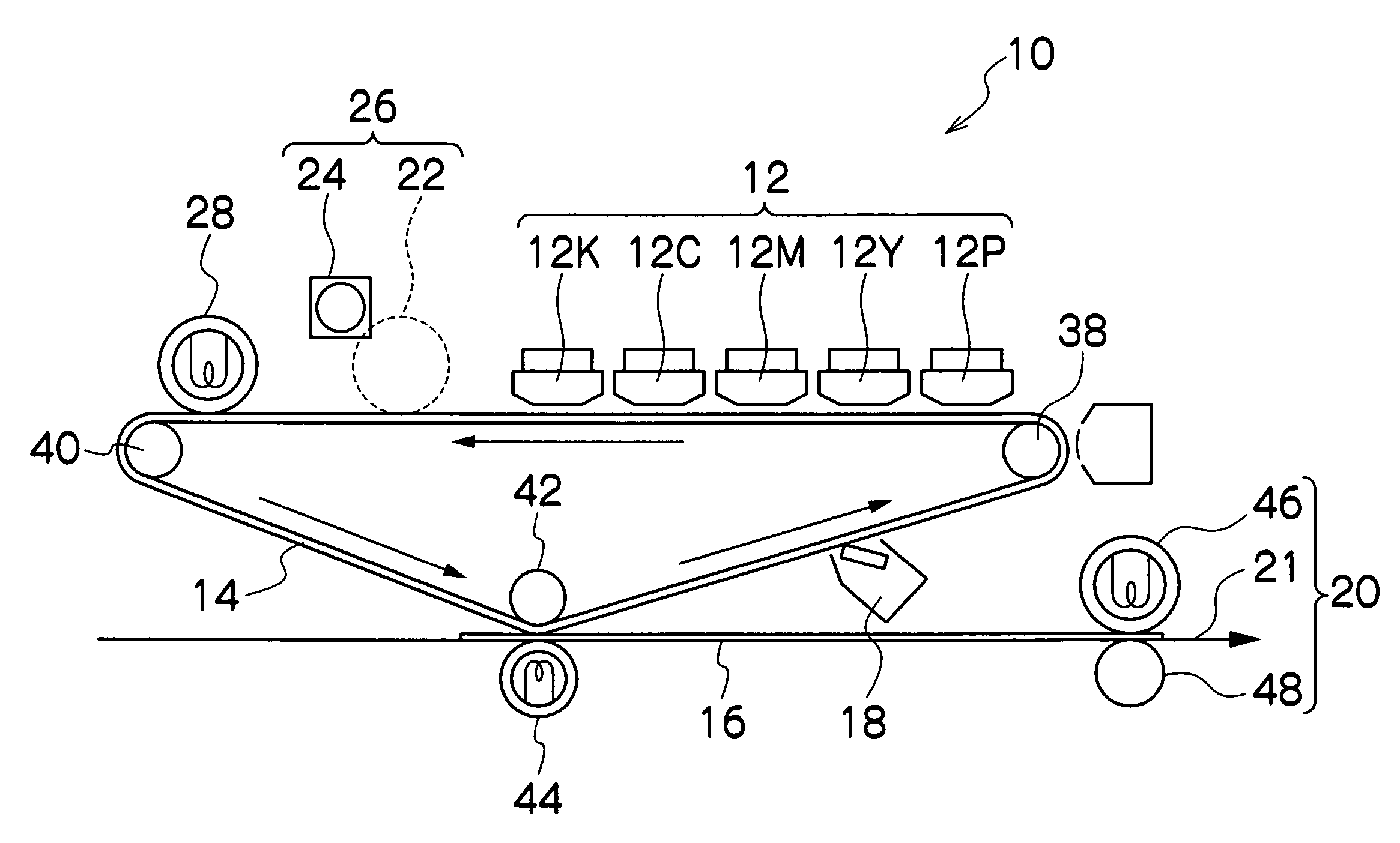
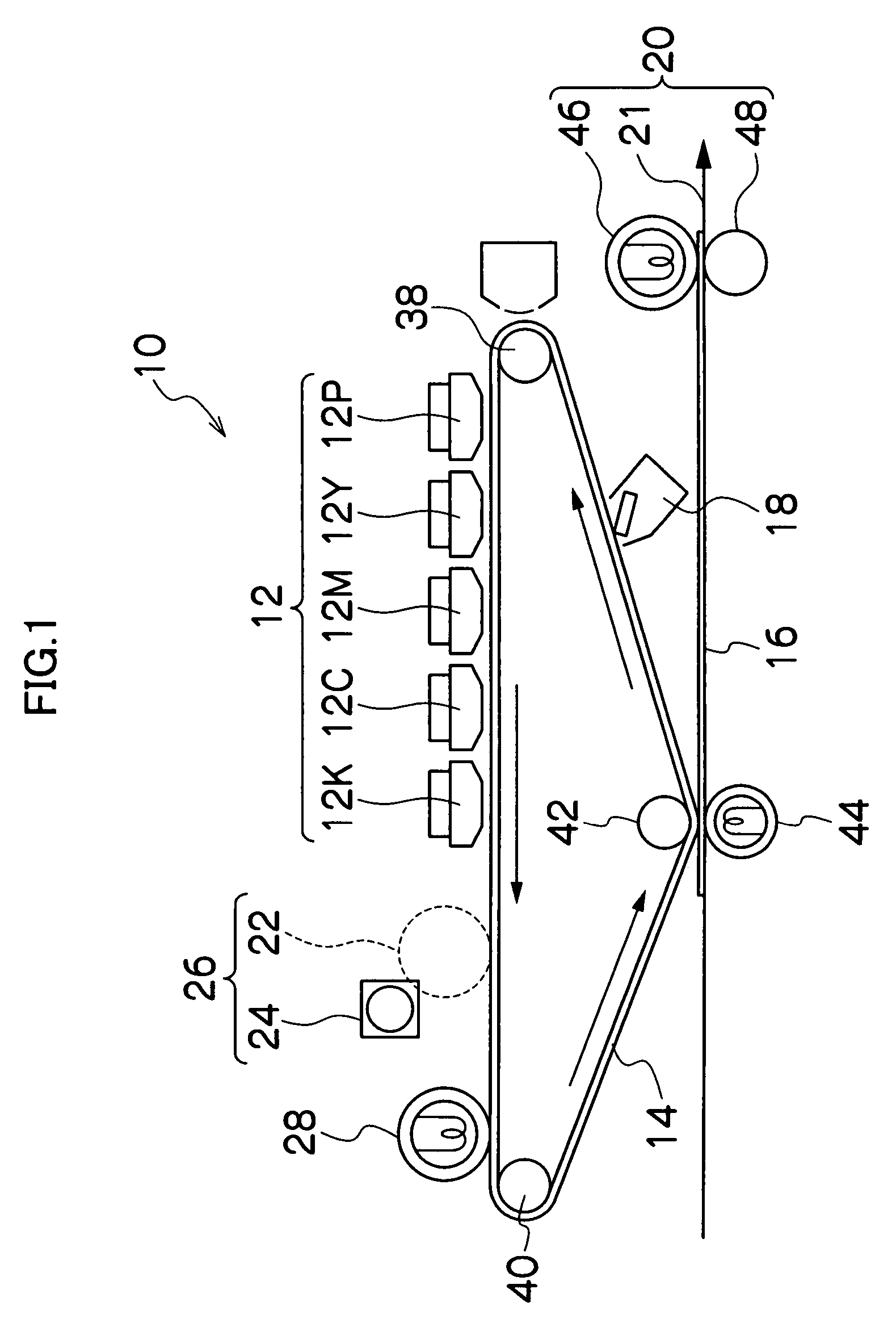
[0051]FIG. 1 is a general schematic drawing showing an inkjet recording apparatus according to an embodiment of the present invention. The inkjet recording apparatus 10 includes an intermediate transfer body, a liquid application device, a solvent removal and drying device, a transfer device, a cleaning device, a fixing device, and the like.

[0052]As shown in FIG. 1, the liquid application device includes a print unit 12, which has a plurality of inkjet heads (hereinafter, called “heads”) 12P, 12Y, 12M, 12C, and 12K respectively corresponding to a treatment liquid (P) forming a first liquid, and four inks of yellow (Y), magenta (M), cyan (C) and black (K) forming second liquids. In the present embodiment, the head 12P is used as a device for applying the treatment liquid, but apart from this, it is also possible to apply the treatment liquid by means of an application roller (not illustrated), or the like.

[0053]In order to apply the treatment ...


PUM


Abstract

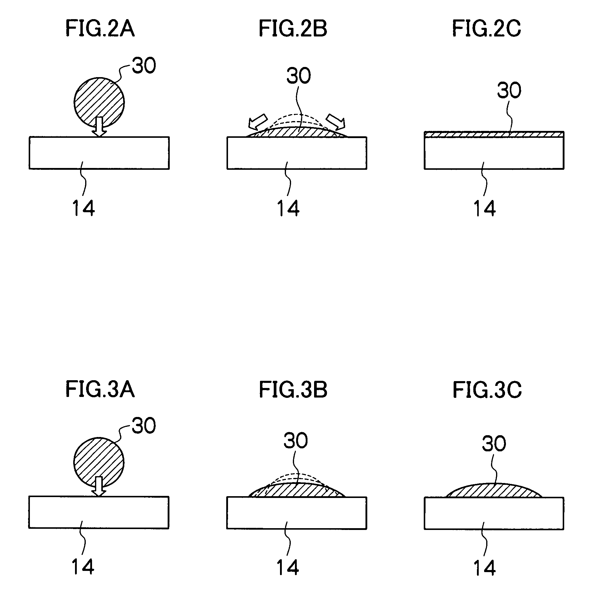
The image forming apparatus includes: an intermediate transfer body; a first liquid application device which applies a first liquid containing an aggregating agent on the intermediate transfer body; a second liquid application device which applies a second liquid containing a solvent-insoluble material on the intermediate transfer body, the solvent-insoluble material being induced to form an aggregate by the aggregating agent to form an image on the intermediate transfer body; and a transfer device which transfers the image formed on the intermediate transfer body to a recording medium, wherein conditions of γt>γ2>γ1 and γg>γ2>γ1 are satisfied, where γt is a surface energy of the intermediate transfer body, γ1 is a surface energy of the first liquid, γ2 is a surface energy of the second liquid, and γg is a surface energy of the aggregate of the solvent-insoluble material.

Description

BACKGROUND OF THE INVENTION[0001]1. Field of the Invention[0002]The present invention relates to an image forming apparatus and image forming method, and more particularly, to an inkjet recording apparatus in which solvent removal and image transfer can be performed without causing image disturbance, by provisionally fixing a solvent-insoluble material, such as coloring material, on an intermediate transfer body prior to the solvent removal and image transfer.[0003]2. Description of the Related Art[0004]An inkjet recording apparatus is provided with an inkjet head (which is hereinafter simply referred to as a “head”) having an ink ejection part including nozzles manufactured by using a high-precision processing technique, still it is difficult to print images on a large number of sheets at high speed by means of a direct recording method known in the related art, under the ejection conditions that have become extremely. Therefore, an inkjet method of intermediate transfer type has b...

Claims


Application Information

Patent Timeline
Patent Type & Authority Patents(United States)
IPC IPC(8): B41J2/01
CPCB41J2/0057
Inventor YAHIRO, YASUKO
Owner FUJIFILM CORP
Learn More