Dynamic spine stabilizer

a spine stabilizer and dynamic technology, applied in the field of spinal stabilizers, can solve the problems of reducing the range of motion, accelerating degeneration at those levels, and affecting the quality of life of people, and achieve the effect of unrestricted angular motion of the spin

Inactive Publication Date: 2010-05-11
YALE UNIV +1
View PDF126 Cites 96 Cited by
  • Summary
  • Abstract
  • Description
  • Claims
  • Application Information

AI Technical Summary

Benefits of technology

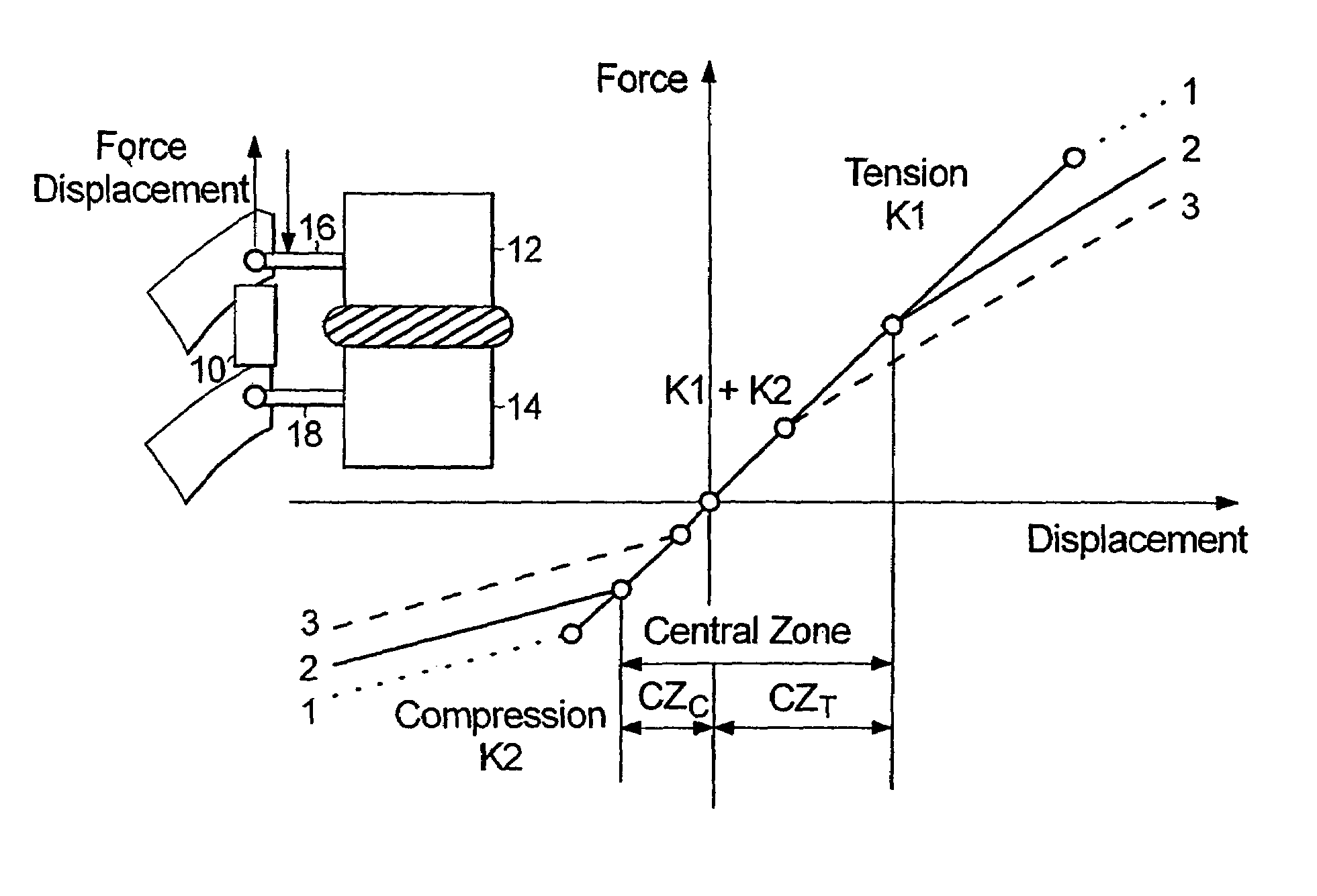
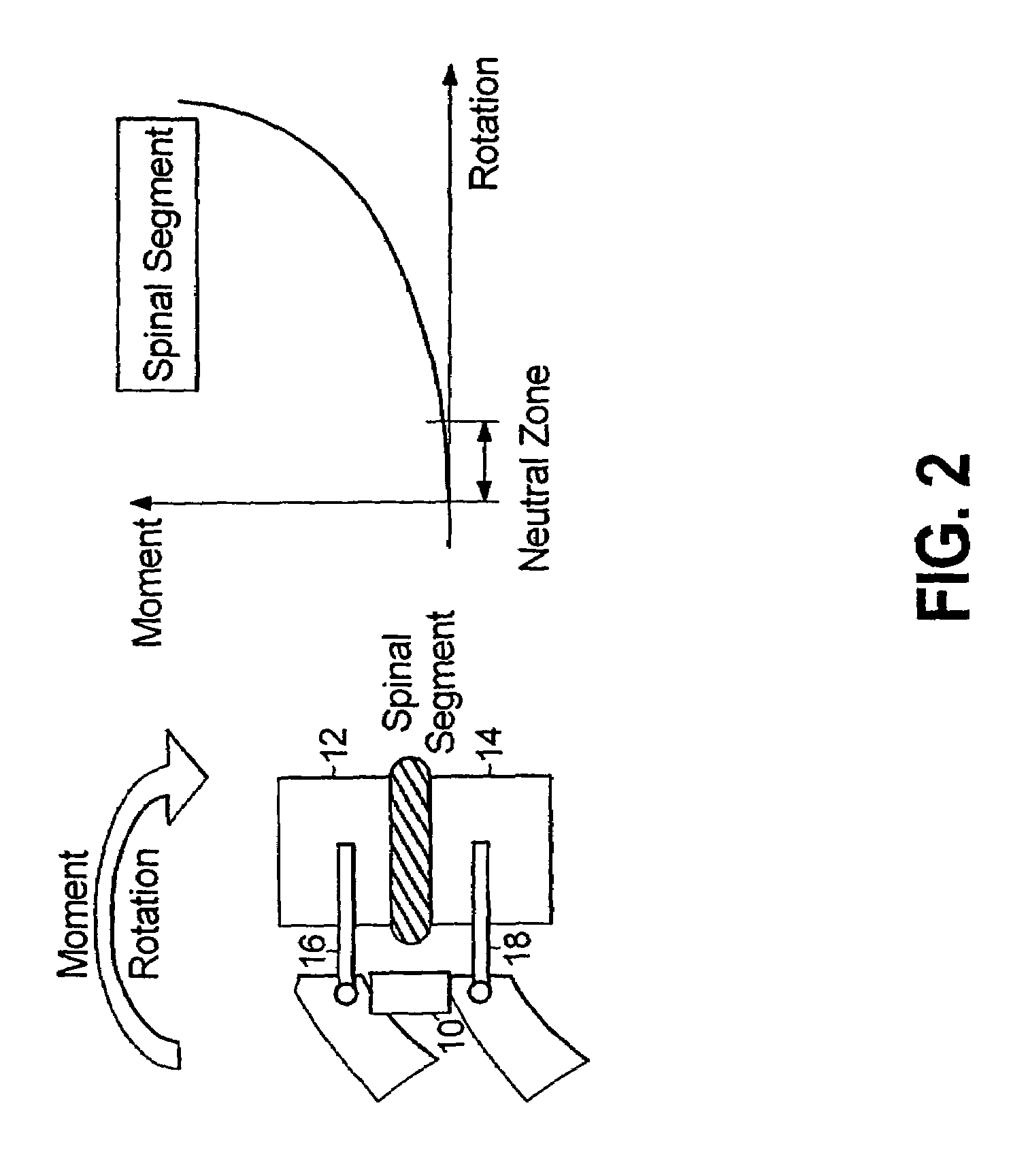
[0012]It is, therefore, an object of the present invention to provide a method for spinal stabilization that provides desirable levels of spinal stabilization while simultaneously permitting substantially unrestricted angular motion of the spine. The advantageous method of the present disclosure is achieved by securing a dynamic stabilizer to vertebrae of a spine and providing mechanical assistance in the form of resistance to a region of the spine to which the dynamic stabilizer is attached. In an exemplary embodiment of the present disclosure, the resistance is applied such that greater mechanical assistance is provided while the spine is around its neutral zone and lesser mechanical assistance is provided while the spine bends beyond its neutral zone.
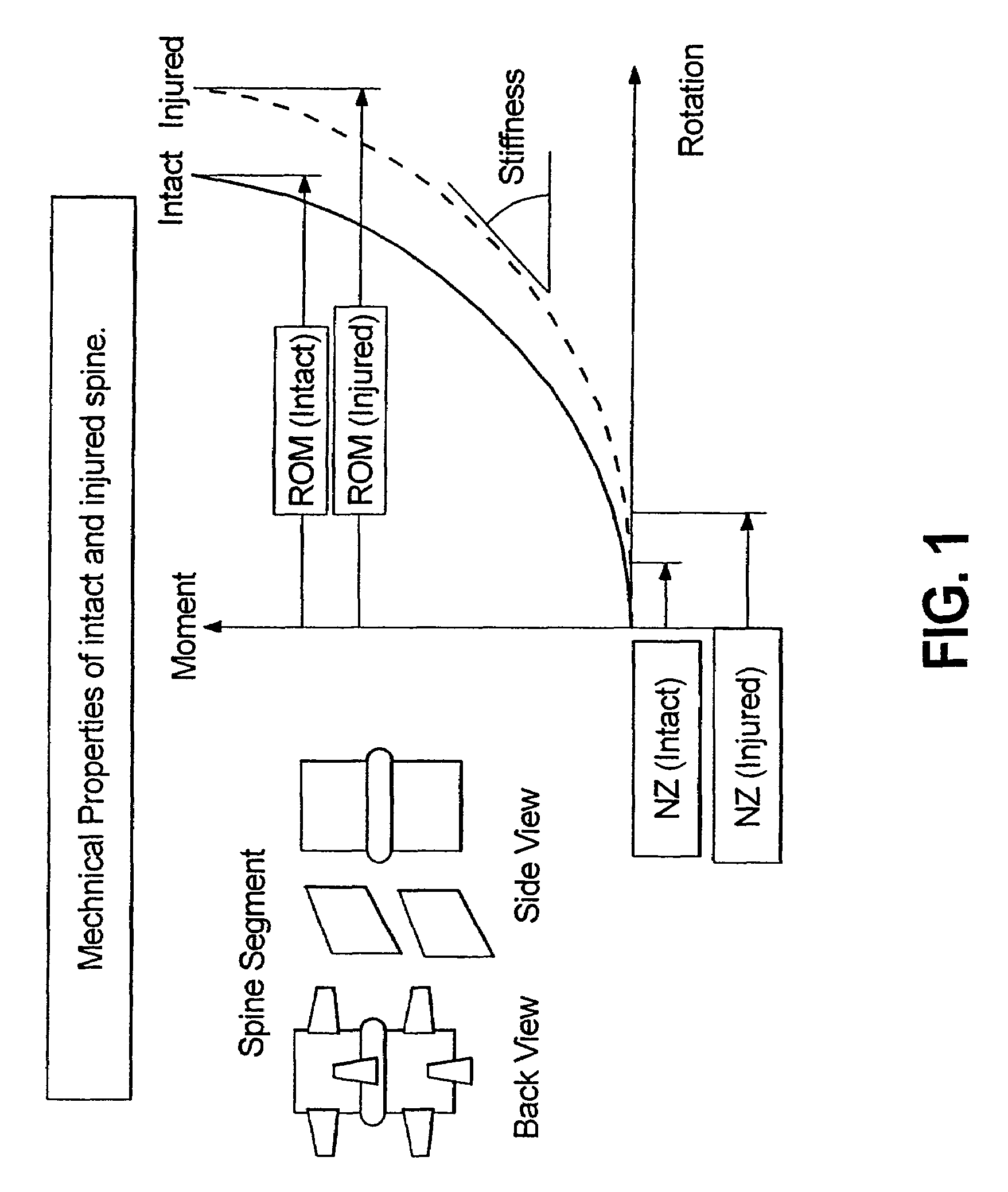
[0015]According to exemplary embodiments of the present disclosure, the dynamic stabilization device, system or apparatus moves under the control of spinal motion, providing increased mechanical support within a central zone corresponding substantially to a neutral zone of an injured spine. Exemplary dynamic stabilization devices include a support assembly and a resistance assembly associated with the support assembly. The resistance assembly generates resistance, applying greater resistance to movement during movement within the central zone and lower resistance to movement beyond the central zone.

Problems solved by technology

Low back pain is one of the most expensive diseases afflicting industrialized societies.
While fusion is effective about seventy percent of the time, there are consequences even to these successful procedures, including a reduced range of motion and an increased load transfer to adjacent levels of the spine, which accelerates degeneration at those levels.
Further, a significant number of back-pain patients, estimated to exceed seven million in the U.S., simply endure chronic low-back pain, rather than risk procedures that may not be appropriate or effective in alleviating their symptoms.
Clinical studies have also found that the range of motion increase does not correlate well with low back pain.

Method used


Image

  • Dynamic spine stabilizer
  • Dynamic spine stabilizer
  • Dynamic spine stabilizer

Examples


Embodiment Construction

[0034]Exemplary embodiments of spinal stabilization devices, systems and apparatus (and associated methods) of the present invention are disclosed herein. It should be understood, however, that the disclosed embodiments are merely exemplary of the invention, which may be embodied in various forms. Therefore, the details disclosed herein are not to be interpreted as limiting, but rather as exemplary teachings that permit persons skilled in the art to make and / or use the disclosed devices, systems and apparatus (and associated methods).

[0035]With reference to FIGS. 2, 3a-c and 4, a method and apparatus are disclosed for spinal stabilization. In accordance with an exemplary embodiment of the present invention, the spinal stabilization method is achieved by securing an internal dynamic spinal stabilization device 10 between adjacent vertebrae 12, 14 and thereby providing mechanical assistance in the form of elastic resistance to the region of the spine to which the dynamic spinal stabil...


PUM


Abstract

A dynamic spine stabilization device is provided that includes at least one force imparting member, e.g., a spring. The force imparting member is adapted to deliver a force of between about 150 lb / inch and 450 lbs / inch, and restrict the relative travel distance between said first and second pedicles to a distance of between about 1.5 mm and 5 mm. The spinal stabilization devices also have a minimal impact on the location of the center of rotation for the spinal segment being treated. By providing resistance in the noted range and restricting the travel distance to the noted range, it has been found that the stabilization device provides a desired level of stabilization, as reflected by range of motion values that closely approximate pre-injury range of motion levels. In addition, the resistance levels are not so high as to alter the location of the center of rotation of the treated spinal segment from its normal anatomical location to levels previously obtained, thereby permitting substantially unimpeded angular motion despite the posterior presence of a stabilization device.

Description

CROSS REFERENCE TO RELATED APPLICATIONS[0001]This application claims the benefit of two provisional patent applications: U.S. Ser. No. 60 / 506,724, entitled “DYNAMIC SPINE STABILIZER”, filed Sep. 30, 2003, and U.S. Ser. No. 60 / 467,414, entitled “DYNAMIC SPINE STABILIZER”, filed May 2, 2003. This application is also a continuation-in-part application that claims the benefit of a, non-provisional patent application: U.S. Ser. No. 10 / 835,109, entitled “DYNAMIC SPINE STABILIZER”, filed Apr. 30, 2004 now U.S. Pat. No. 7,029,475. The contents of each of the foregoing applications is incorporated herein by reference.BACKGROUND OF THE INVENTION[0002]1. Field of the Invention[0003]The invention relates to a method and apparatus for spinal stabilization. More particularly, the invention relates to a spinal stabilization device, system and / or apparatus (and associated methods) that deliver desirable levels of stabilization to a spine while maintaining or preserving physiologically desirable lev...

Claims


Application Information

Patent Timeline
Patent Type & Authority Patents(United States)
IPC IPC(8): A61B17/70A61B17/56A61B17/58A61F
CPCA61B17/7028A61B17/7025A61B17/7007A61B17/7004A61F5/01A61F5/00
Inventor TIMM, JENS PETERPANJABI, MANOHAR M.
Owner YALE UNIV
Why Eureka
Try Eureka