Detection of air filter clogging and provision of emergency ventilation in an outdoor electronics cabinet cooled by ambient forced air

a technology for outdoor electronics and enclosures, applied in ventilation systems, fire alarms, instruments, etc., can solve problems such as loss of service to wireless customers, cell phone subscribers, and air filters that are associated with openings, and can not be used in emergency ventilation

Active Publication Date: 2010-05-11
COMMSCOPE TECH LLC
View PDF61 Cites 16 Cited by
  • Summary
  • Abstract
  • Description
  • Claims
  • Application Information

AI Technical Summary

Problems solved by technology

During use, the openings, or the air filters associated therewith, might become clogged, such as from particulate debris in the circulating air or from large obstructions, such a sheet of paper being drawn up against the inlet openings.
With the blocked or restricted forced airflow through the pressurized electronic cabinet, the electronic modules, or components therein, such as amplifiers, may overheat.
However, as may be appreciated, such a shut down of the electronics results in the loss of service to the wireless customers, such as cell phone subscribers.
However, such air speed sensors only detect localized airflow, and, therefore, are susceptible to issuing false alarms.
For example, clogging of the air filter in the immediate vicinity of a sensor can result in a local reduction in the airflow.
However, the remainder of the filter might be unrestricted.
Or other filters may be unclogged and operating properly.
Thus, any alarm condition would be unnecessary.
However, in practice, the alarm points for such high temperature alarms are often set so low that false alarms are issued.
Both such conditions are undesirable.
Furthermore, a temperature detector only detects the overheating of an electronics module.
For example, if the ambient temperature around the cabinet is high, and the inlet openings and filters become clogged, a high temperature cabinet alarm may issue.
However, such fan failure alarms are often logically OR'd with a high temperature cabinet alarm.

Method used


Image

  • Detection of air filter clogging and provision of emergency ventilation in an outdoor electronics cabinet cooled by ambient forced air
  • Detection of air filter clogging and provision of emergency ventilation in an outdoor electronics cabinet cooled by ambient forced air
  • Detection of air filter clogging and provision of emergency ventilation in an outdoor electronics cabinet cooled by ambient forced air

Examples


Embodiment Construction

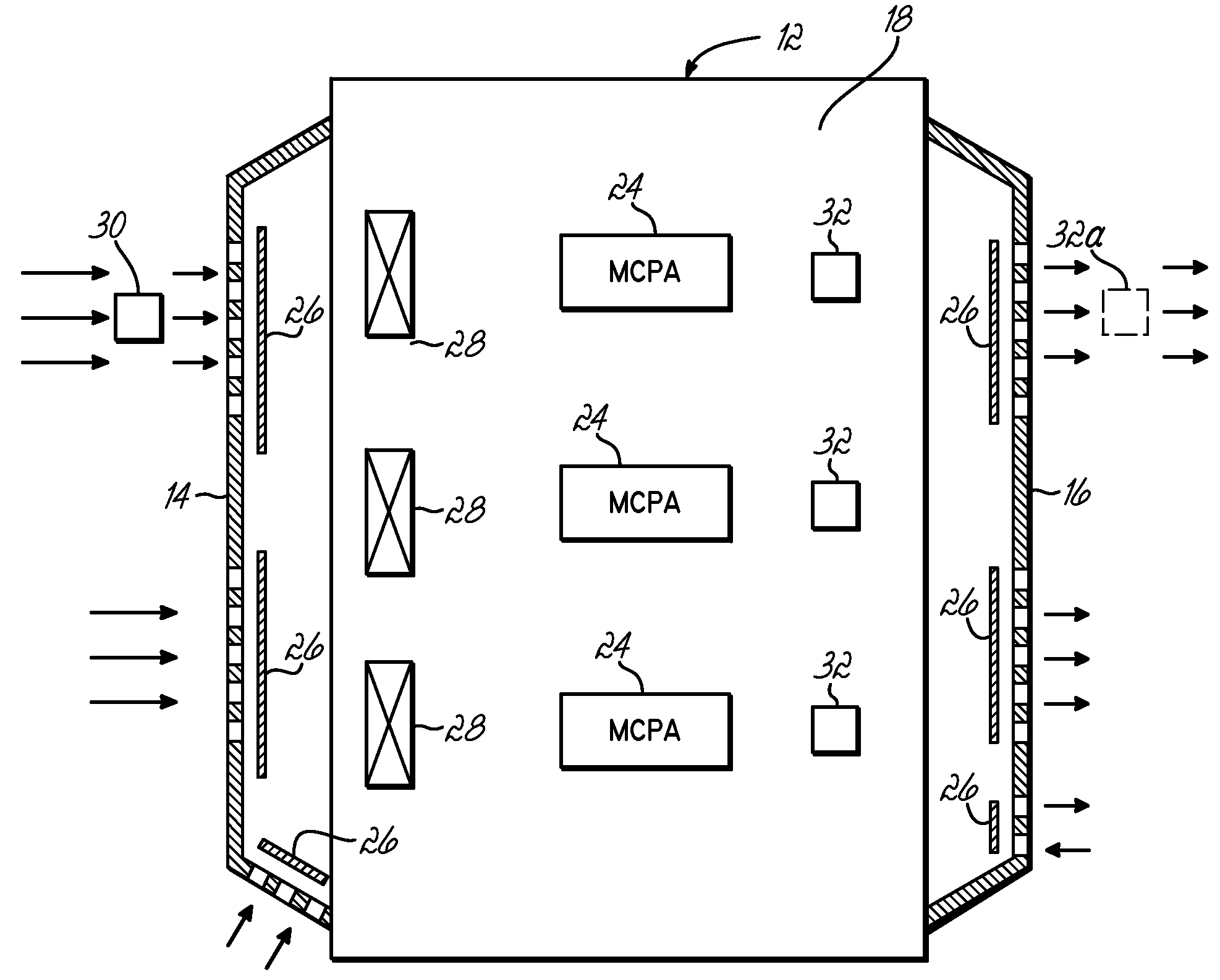
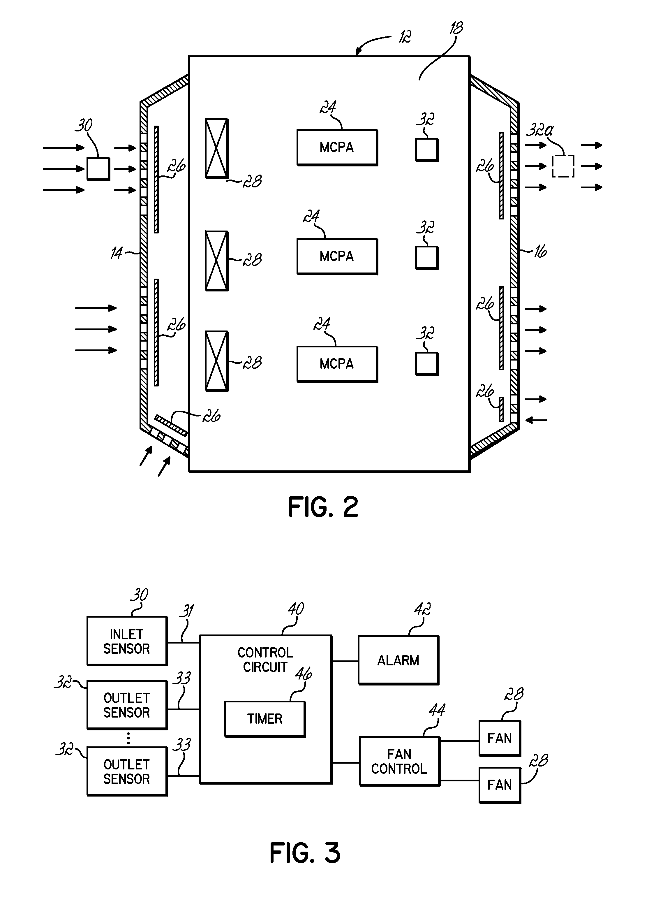
[0013]The present invention addresses various of the issues noted above, and other drawbacks of the prior art by providing a ventilation system that utilizes a detection mechanism for monitoring airflow in an enclosure that has an interior space cooled with forced ambient air. A first thermal sensor measures ambient air temperature, and the second thermal sensor measures the temperature of heated air that is exiting the electronics in the cabinet that are to be cooled. For example, if amplifiers, such as MCPA's, are to be cooled, the second sensor is located in the exit air stream of the MCPA's. A control circuit receives outputs from each sensor, and determines the temperature differential between the measured temperatures. When the temperature differential exceeds a set point, thus indicating restricted airflow in the enclosure, an alarm is initiated. Various other steps might be taken prior to initiating an alarm to address the blocked condition. Furthermore, the present inventio...


PUM


Abstract

A detection mechanism for monitoring airflow in an electronics enclosure includes a first thermal sensor positioned proximate the enclosure for measuring an ambient air temperature and a second thermal sensor positioned proximate an exit air stream for measuring the temperature of air that is heated by the electronics in the enclosure. A control circuit is coupled with the first and second thermal sensors and is configured for determining a temperature differential between the measured temperatures of the thermal sensors. The control circuit may initiate an alarm when the temperature differential exceeds a setpoint thereby indicating restricted airflow in the enclosure. The control circuit might also take other remedial steps prior to initiating the alarm.

Description

FIELD OF THE INVENTION[0001]This invention generally relates to enclosures for housing electronics components, and particularly, to enclosures that are ventilated for the dissipation of heat generated by the electronic components.BACKGROUND OF THE INVENTION[0002]Electronics enclosures, such as cabinets, are utilized for storing, housing, and protecting various electronics, such as those utilized for wireless or cellular communications. For example, pressurized outdoor electronic cabinets are often utilized to house electronic modules, such as multi-carrier power amplifiers (MCPA's) that generate significant amounts of heat. For cooling the electronics, the cabinets, or other enclosures, are ventilated such that ambient air is drawn into the cabinet and through the interior space of the cabinet to circulate around the electronic components, before being exhausted to the outside of the cabinet. To that end, generally, such cabinets utilize one or more inlet or intake openings that are...

Claims


Application Information

Patent Timeline
Patent Type & Authority Patents(United States)
IPC IPC(8): G08B17/00
CPCH05K7/207H05K7/20181
Inventor PALASZEWSKI, STEPHEN
Owner COMMSCOPE TECH LLC
Why Eureka
Try Eureka