Muscle energy converter with smooth continuous tissue interface

a tissue interface and muscle energy technology, applied in the direction of dynamo-electric components, dynamo-electric machines, therapy, etc., can solve the problems of electrical conduits comprised of wires and tubes penetrating the skin, electrical cross-coupling of trans-integumental transformers, and the risk of power-draining electromagnetic cross-coupling

Inactive Publication Date: 2010-05-11
UNIVERSITY OF CINCINNATI
View PDF130 Cites 41 Cited by
  • Summary
  • Abstract
  • Description
  • Claims
  • Application Information

AI Technical Summary

Problems solved by technology

Present apparatus and methods for delivering power to active heart-failure treatment devices or non-cardiac devices with similar energy requirements may be problematic.
For example, power conduits comprised of wires and tubes penetrating the skin may become infected.
Similarly, trans-integumental transformers may present the risk of power-draining electromagnetic cross-coupling.
Neither nuclear nor chemical batteries have proven to be effective for powering quantities beyond those of pacemakers and defibrillators.
Likewise, power supply limitations and issues limit the practicality of various non-cardiac devices as well.
The requirement of methods of transferring the power to an active circulatory support device, however, has not been demonstrated to be reliable over extended time periods notwithstanding, for example, the teachings of hydraulic systems in U.S. Pat. No. 5,888,186 to Trumble, U.S. Pat. No. 5,718,248 to Magovern and U.S. Pat. Nos. 5,984,857; 5,701,919; 5,653,676; and 5,344,385, all assigned to Thoratec, Inc.
The limitations of these devices taught in the prior art (referenced above) lie in the imposed movement of discrete parts through tissue required by their respective operations, which may result in an increased potential for scarring tissue which may tend to immobilize and limit motion.
These devices are also limited by their physical bulk and by the potential of hydraulic seals to fail in their welded metal bellows or piston mechanisms.

Method used


Image

  • Muscle energy converter with smooth continuous tissue interface
  • Muscle energy converter with smooth continuous tissue interface
  • Muscle energy converter with smooth continuous tissue interface

Examples


Embodiment Construction

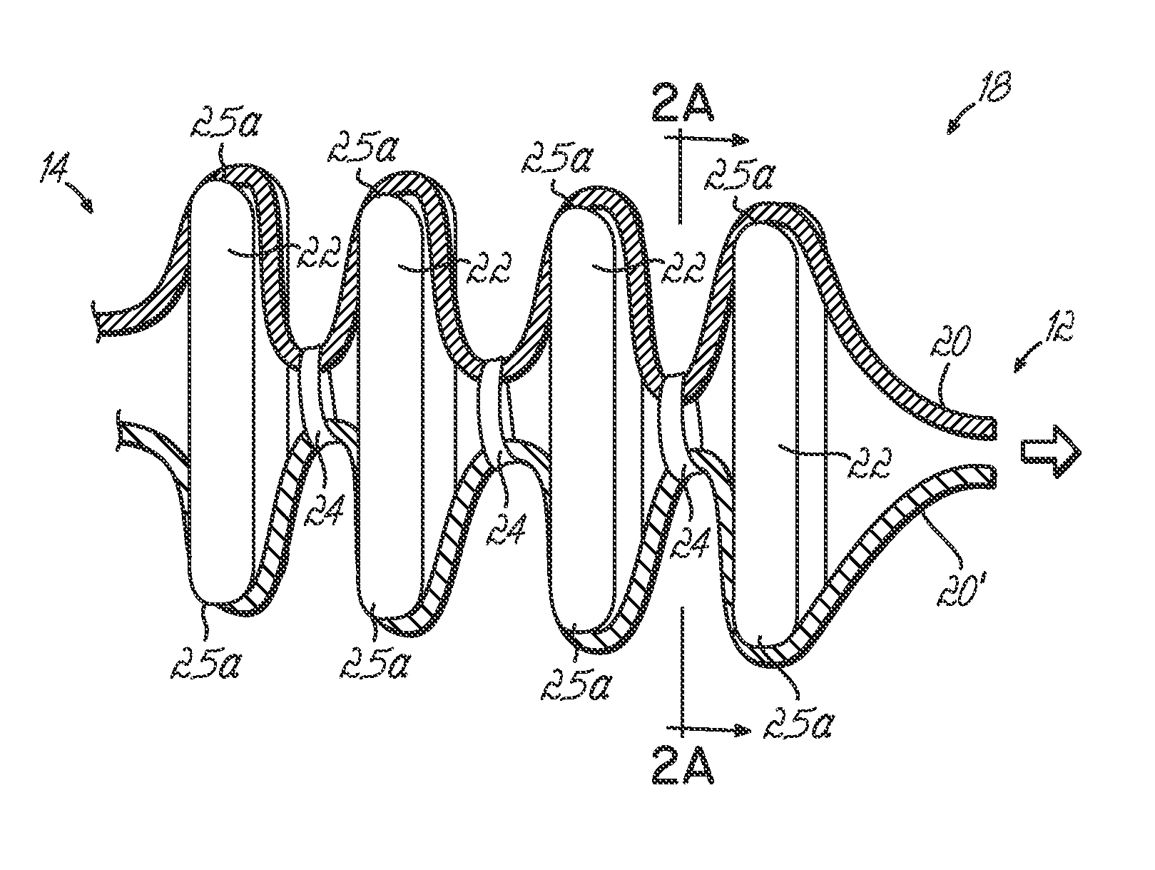
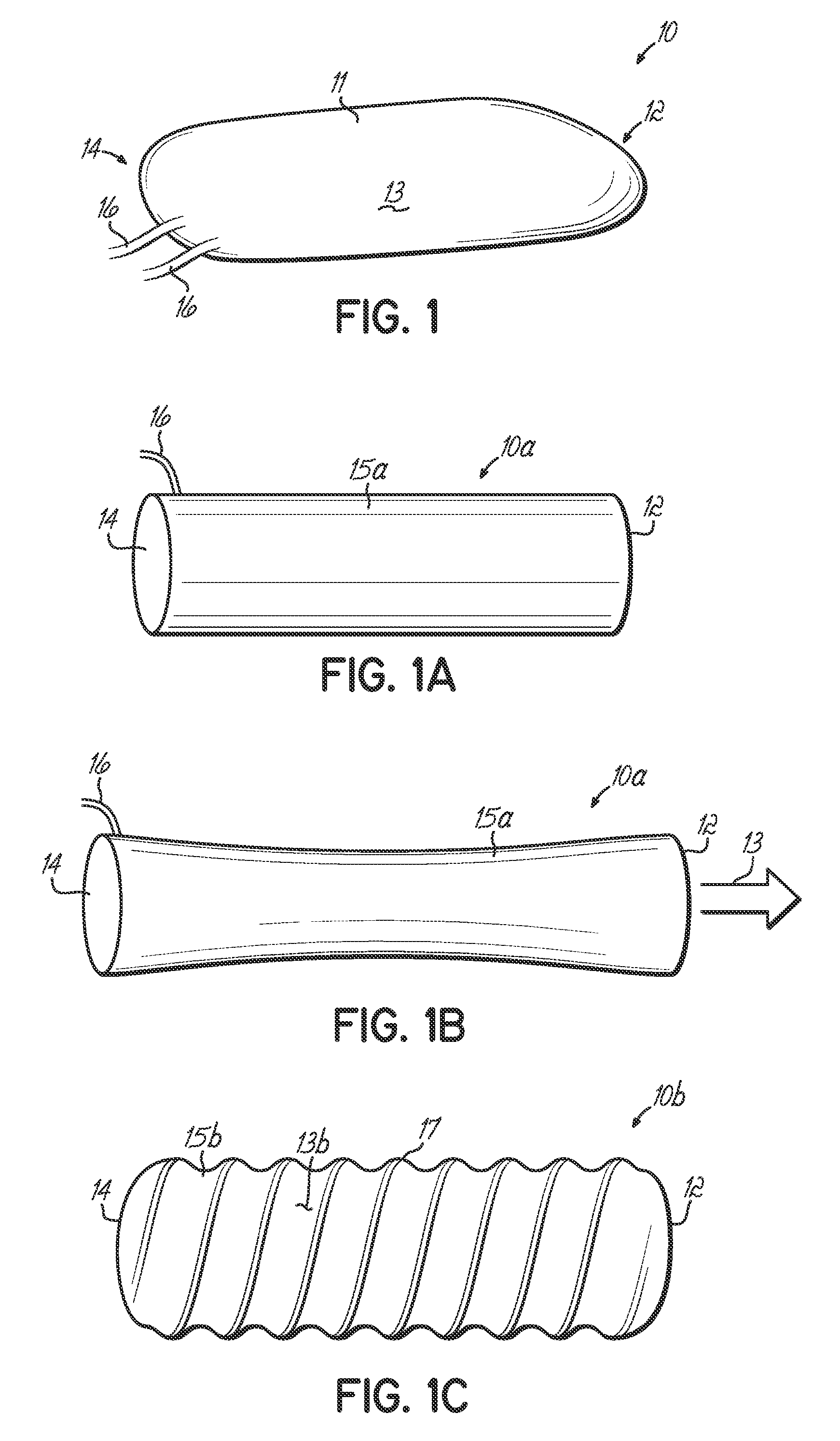
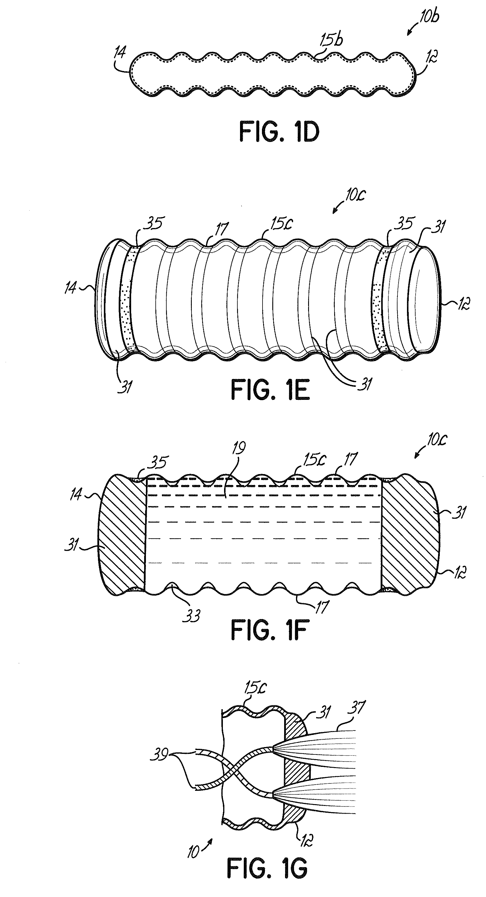
[0045]With reference to FIG. 1, a converter 10 is an elongated structure generally having a length and width similar to those of the tendon of a muscle (not shown) to which they are applied and a thickness not exceeding an order of magnitude greater than the thickness of the native tendon. Converter 10 has a body 11 having a tissue-facing surface 13, a mobile end 12 and a longitudinally opposed relatively stationary end 14. One or more energy conduits 16 protrude from the relatively stationary end 14 to conduct energy from the converter 10 to a power-consuming device (not shown) such as a circulatory device utilizing the energy from the converter 10. Energy conduits 16 may comprise, for example, electrical wires, hydraulic tubes, mechanical conduits such as a cable-in-sheath, or any other suitable mechanism.

[0046]The mobile end 12 of the converter 10 is connected to a muscle at a point proximate the musculotendinous junction. Methods of connecting the converter 10 may for example in...


PUM


Abstract

A device and corresponding method for converting the contractile work of skeletal muscles into transportable energy. The device may comprise a converter having a mobile end adapted to be connected to a skeletal muscle, a relatively stationary end opposite the mobile end; one or more energy processing units operatively connected to the mobile and stationary ends of the converter, with each energy processing unit adapted to convert tensile forces generated by contraction of the skeletal muscle into transportable energy; and one or more energy conduits such as electrical wires associated with the relatively stationary end of the converter for delivering the transportable energy to power-consuming devices implanted in a body. The device may further comprise a relatively stationary end that is operatively connected to a body structure that is stationary relative to the skeletal muscle.

Description

CROSS REFERENCE TO RELATED APPLICATIONS[0001]Benefit is claimed of the filing date of Oct. 18, 2005 of U.S. provisional patent application Ser. No. 60 / 727,650. Such application is expressly incorporated herein by reference as if fully set forth herein.FIELD OF THE INVENTION[0002]The present invention relates to apparatus for delivering energy from muscles to power devices such as heart-failure treatment devices, non-cardiac devices, or other power consuming devices.BACKGROUND OF THE INVENTION[0003]Present apparatus and methods for delivering power to active heart-failure treatment devices or non-cardiac devices with similar energy requirements may be problematic. For example, power conduits comprised of wires and tubes penetrating the skin may become infected. Similarly, trans-integumental transformers may present the risk of power-draining electromagnetic cross-coupling. Neither nuclear nor chemical batteries have proven to be effective for powering quantities beyond those of pacem...

Claims


Application Information

Patent Timeline
Patent Type & Authority Patents(United States)
IPC IPC(8): A61N1/378
CPCA61N1/3785H02K7/1823H02K35/02H02K7/1876H02K7/1853
Inventor MELVIN, DAVID BOYD
Owner UNIVERSITY OF CINCINNATI
Why Eureka
Try Eureka