Method of attaching a diaphragm to a frame for a planar loudspeaker
What is Al technical title?
Al technical title is built by PatSnap Al team. It summarizes the technical point description of the patent document.
a technology of diaphragms and loudspeakers, applied in the field of electrodynamic loudspeakers, can solve the problems of not being able to position or orient the desired loudspeaker, using a loudspeaker, and difficult to achieve the desired performance of the audio system
Inactive Publication Date: 2010-05-18
HARMAN INT IND INC +1
View PDF42 Cites 9 Cited by
Summary
Abstract
Description
Claims
Application Information
AI Technical Summary
This helps you quickly interpret patents by identifying the three key elements:
Problems solved by technology
Method used
Benefits of technology
Problems solved by technology
Many design and manufacturing challenges present themselves in the manufacturing of electro-dynamic loudspeakers.
Accordingly, designing conductors for electro-dynamic loudspeaker applications presents various challenges such as selecting the speaker with the desired audible output for a given location that will fit within the size and location constraints of the desired applications environment.
Often, space limitations in the listening environment prohibit the use of a loudspeaker in an audio system that possesses the preferred directivity pattern for the system's design.
For example, the amount of space and the particular locations available in a listening environment for locating and / or mounting the loudspeakers of the audio system may prohibit the use of a particular loudspeaker that exhibits the intended directivity pattern.
Also, due to space and location constraints, it may not be possible to position or oriented the desired loudspeaker in a manner consistent with the loudspeaker's directivity pattern.
Consequently, size and space constraints of a particular environment may make it difficult to achieve the desired performance from the audio system.
Unfortunately, the large rectangular size results in a high-frequency beam width angle or coverage that may be too narrow for its intended application.
Method used
Image
Click on the blue label to locate the original text in one second.
Reading with bidirectional positioning of images and text.
Examples
Embodiment Construction
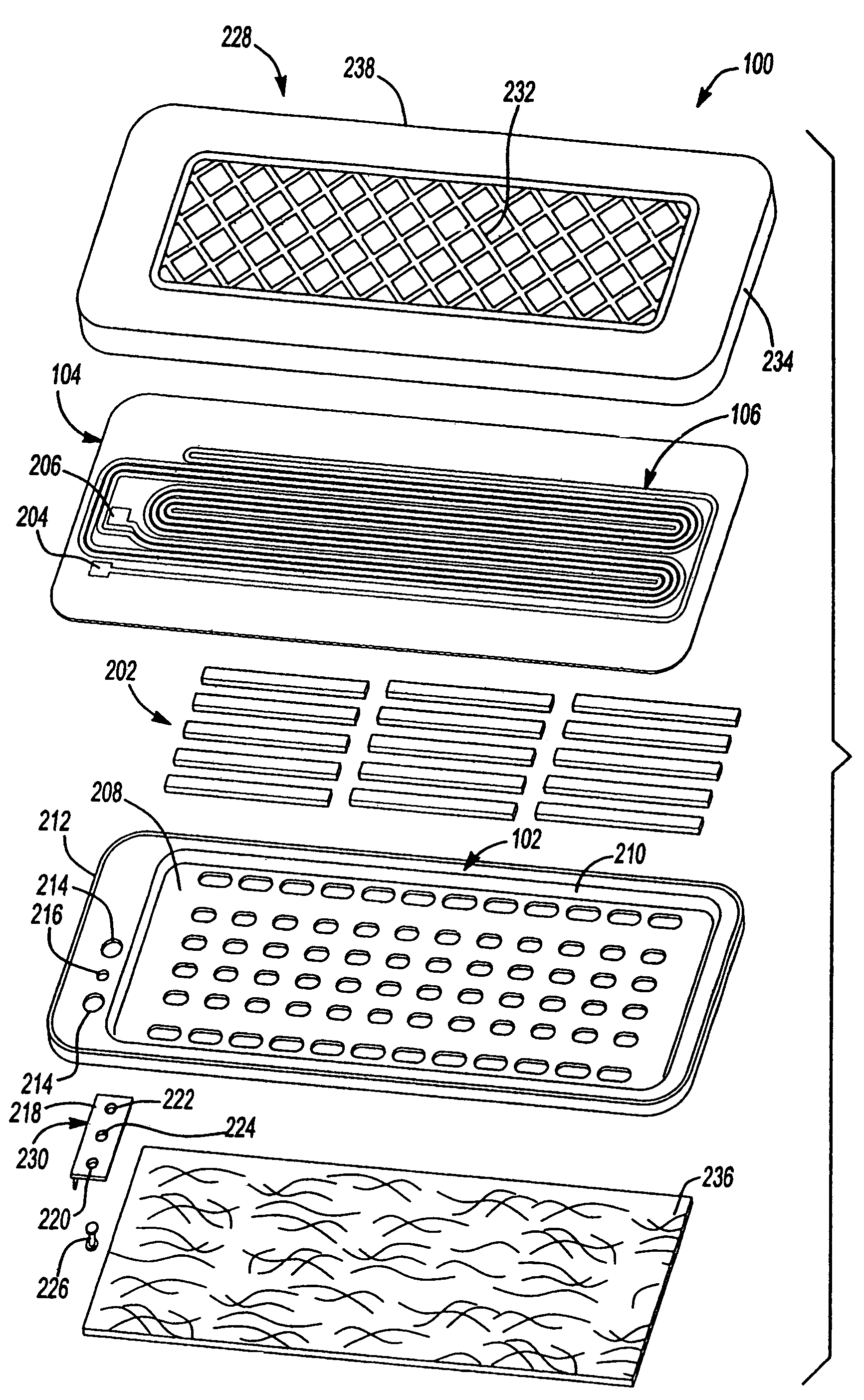
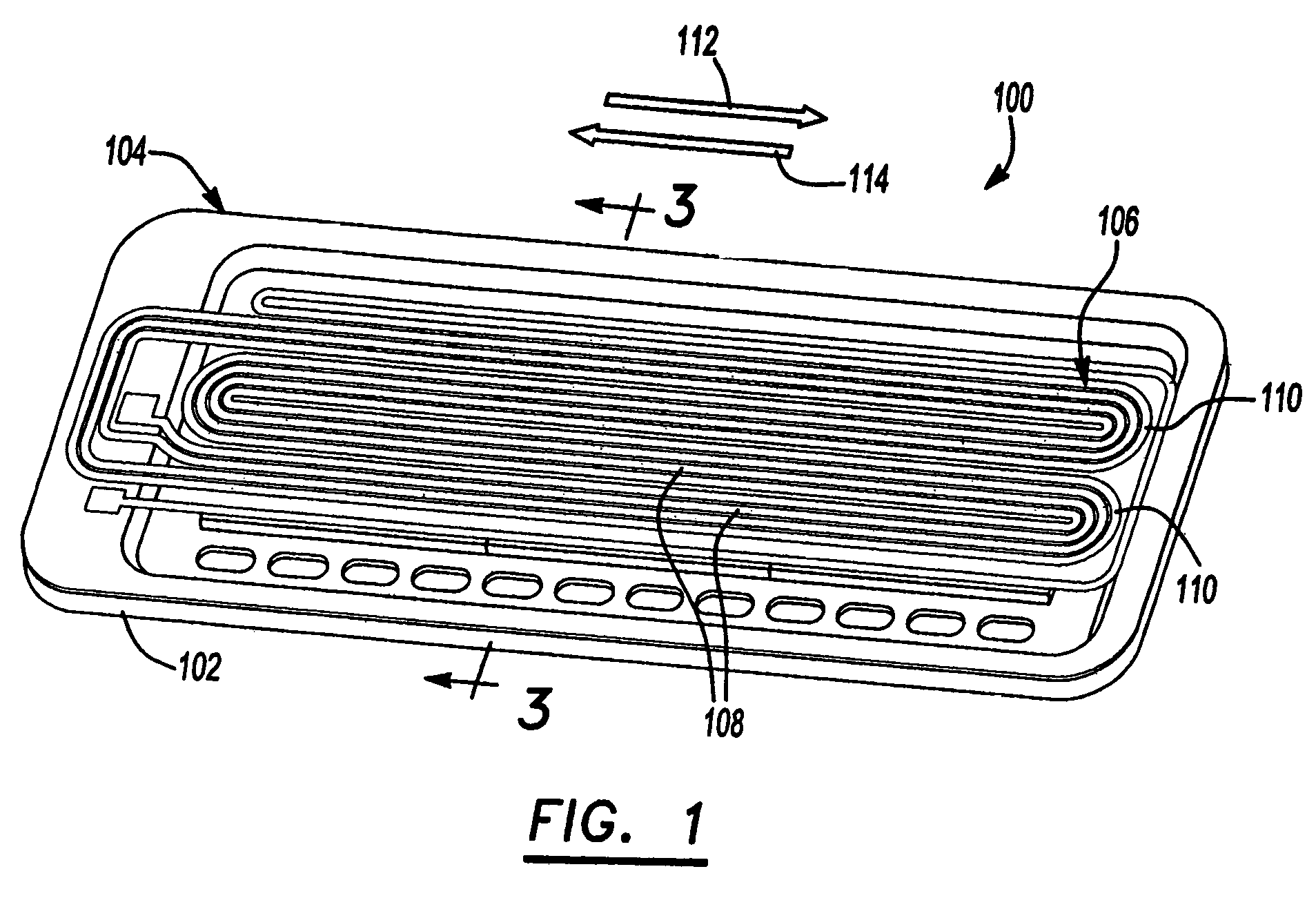
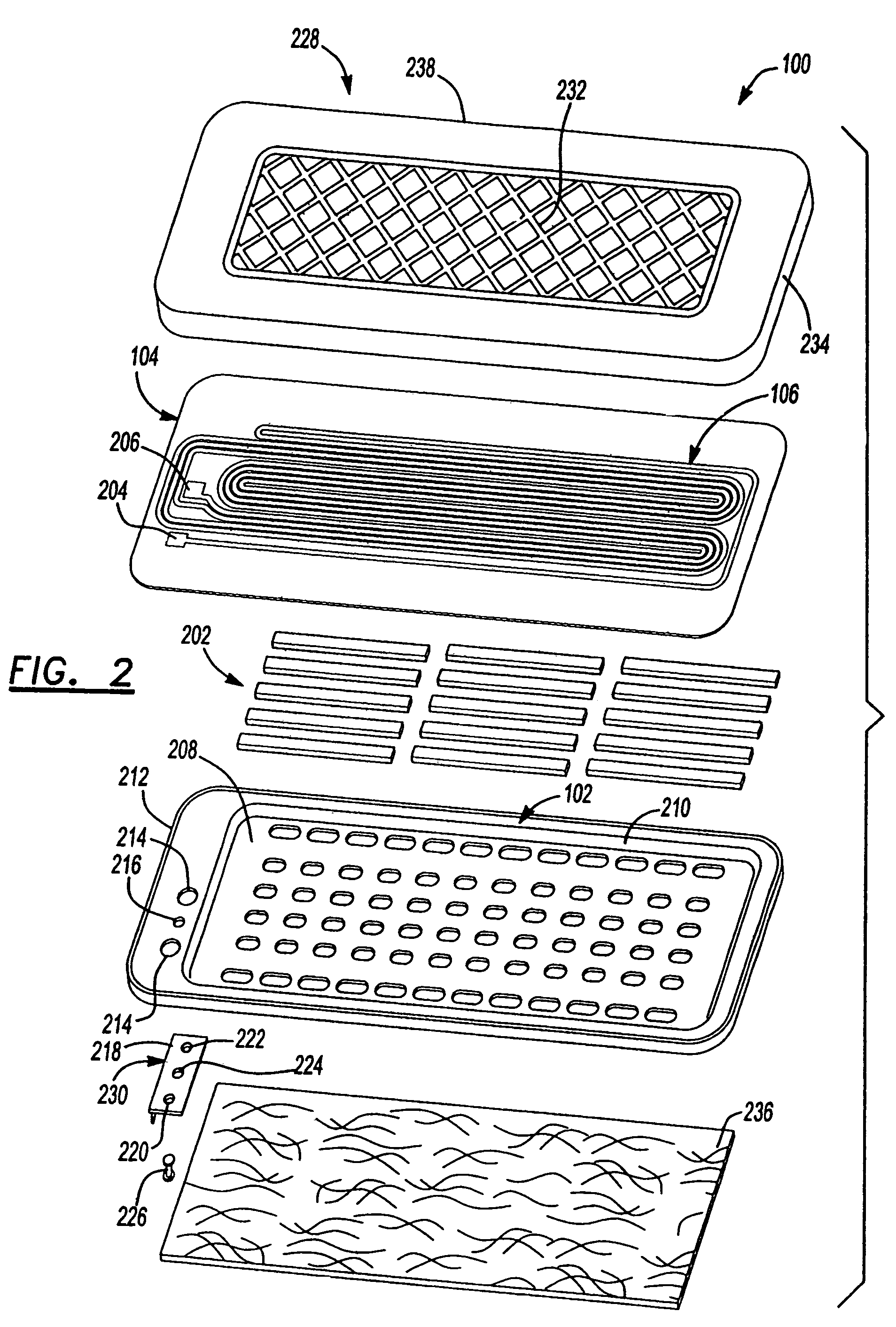
[0068]FIG. 1 is a perspective view of an electro-dynamic loudspeaker 100 of the invention. As shown in FIG. 1, the electro-dynamic loudspeaker is a generally planar loudspeaker having a frame 102 with a diaphragm 104 attached in tension to the frame 102. A conductor 106 is positioned on the diaphragm 104. The conductor 106 is shaped in serpentine fashion having a plurality of substantially linear sections (or traces) 108 longitudinally extending along the diaphragm interconnected by radii 110 to form a single current path. Permanent magnets 202 (shown in FIG. 2) are positioned on the frame 102 underneath the diaphragm 104, creating a magnetic field.
[0069]Linear sections 108 are positioned within the flux fields generated by permanent magnets 202. The linear sections 108 carry current in a first direction 112 and are positioned within magnetic flux fields having similar directional polarization. Linear sections 108 of conductor 106 having current flowing in a second direction 114, th...
PUM
Property
Measurement
Unit
thickness
aaaaa
aaaaa
shape
aaaaa
aaaaa
perimeter
aaaaa
aaaaa
Abstract
Electro-dynamic loudspeakers typically include a diaphragm having a conductor applied to one of its surfaces where the diaphragm is secured to a frame. The conductor is connected to a power supply for providing electrical current through linear traces of the conductor that interact with magnetic fields generated by magnets that are mounted to the frame. The diaphragm is driven by a motive force created when current passes through the conductor within the magnetic field. The electrical current is varied to create an acoustical output from the electro-dynamic loudspeaker. Different methods of attaching the diaphragm are provided for simplifying the manufacturing process and for obtaining a robust electro-dynamic loudspeaker.
Description
CROSS-REFERENCE TO RELATED APPLICATIONS[0001]This divisional application claims the benefit of U.S. patent application Ser. No. 10 / 428,316, filed on 2 May 2003 now abandoned which claims the benefit of U.S. Provisional Application No. 60 / 391,134, filed on 24 Jun. 2002, U.S. Provisional Application No. 60 / 378,188, filed on 6 May 2002 and U.S. Provisional Application No. 60 / 380,001, filed on 2 May 2002. The disclosure of U.S. patent application Ser. No. 10 / 426,316 is incorporated herein by reference.[0002]This application also incorporates by reference the disclosures of each of the following concurrently filed with U.S. patent application (parent application) Ser. No. 10 / 428,316: U.S. Pat. No. 7,155,026, entitled “Mounting Bracket System,” filed 2 May 2003; U.S. Pat. No. 7,278,200, entitled “Method Of Tensioning A Diaphragm For An Electro-Dynamic Loudspeaker,” filed 2 May 2003; U.S. Pat. No. 7,152,299, entitled “Method Of Assembling A Loudspeaker,” filed 2 May 2003; U.S. Pat. No. 7,1...
Claims
Application Information
Patent Timeline
Application Date:The date an application was filed.
Publication Date:The date a patent or application was officially published.
First Publication Date:The earliest publication date of a patent with the same application number.
Issue Date:Publication date of the patent grant document.
PCT Entry Date:The Entry date of PCT National Phase.
Estimated Expiry Date:The statutory expiry date of a patent right according to the Patent Law, and it is the longest term of protection that the patent right can achieve without the termination of the patent right due to other reasons(Term extension factor has been taken into account ).
Invalid Date:Actual expiry date is based on effective date or publication date of legal transaction data of invalid patent.