Macro inspection apparatus and microscopic inspection method

a microscope and inspection apparatus technology, applied in the field of microscope inspection apparatus and method, can solve the problems of inability to use a method for a film, and the limitation of conventional methods using interference light, so as to achieve high sensitivity

Inactive Publication Date: 2010-05-18
INT BUSINESS MASCH CORP
View PDF7 Cites 17 Cited by
  • Summary
  • Abstract
  • Description
  • Claims
  • Application Information

AI Technical Summary

Problems solved by technology

However, this method cannot be used for a film in which no interference occurs or a film through which no light is transmitted.
That is, the conventional method using interference light has a limitation that only a light transmitting film can be inspected.

Method used


Image

  • Macro inspection apparatus and microscopic inspection method
  • Macro inspection apparatus and microscopic inspection method
  • Macro inspection apparatus and microscopic inspection method

Examples


Embodiment Construction

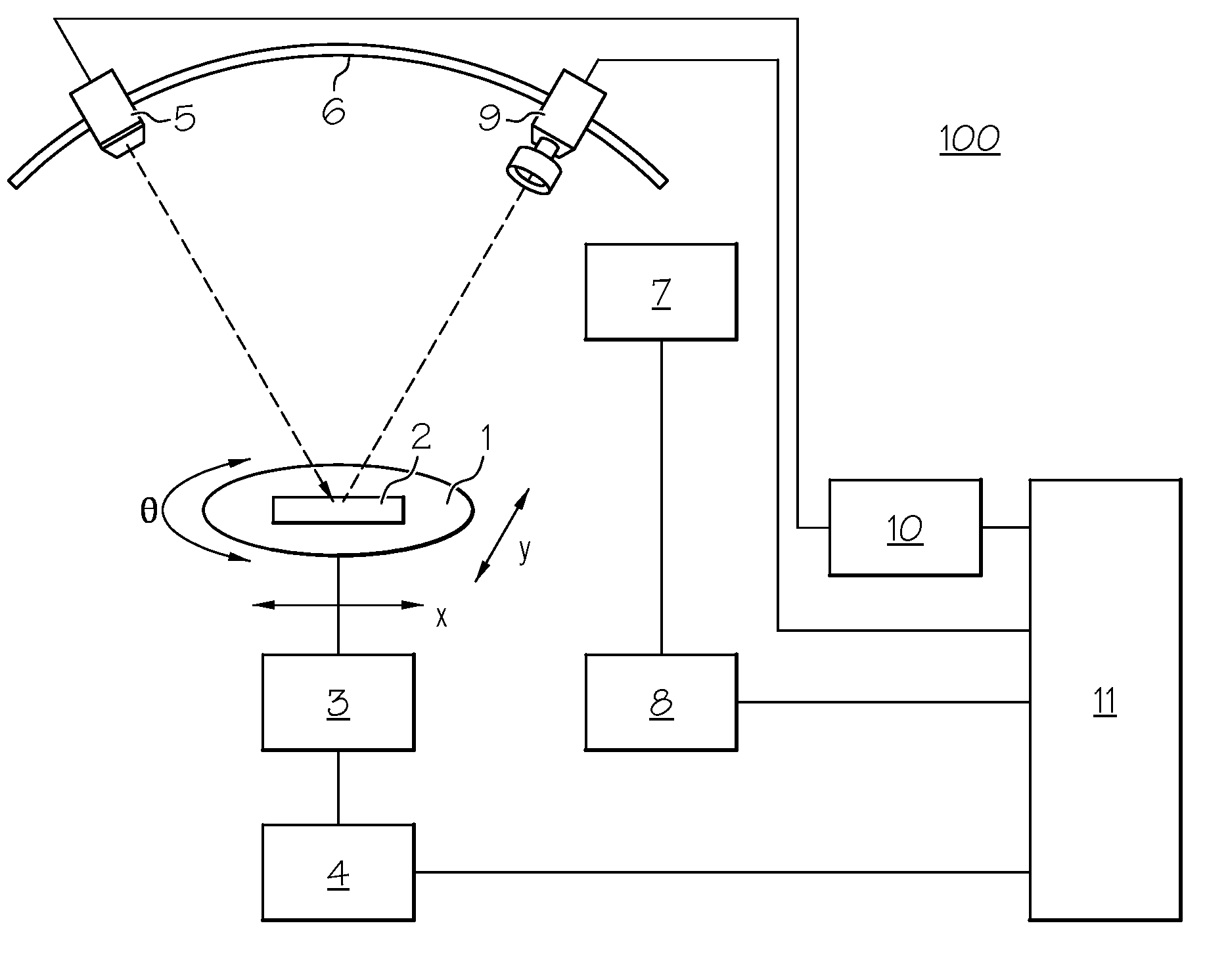
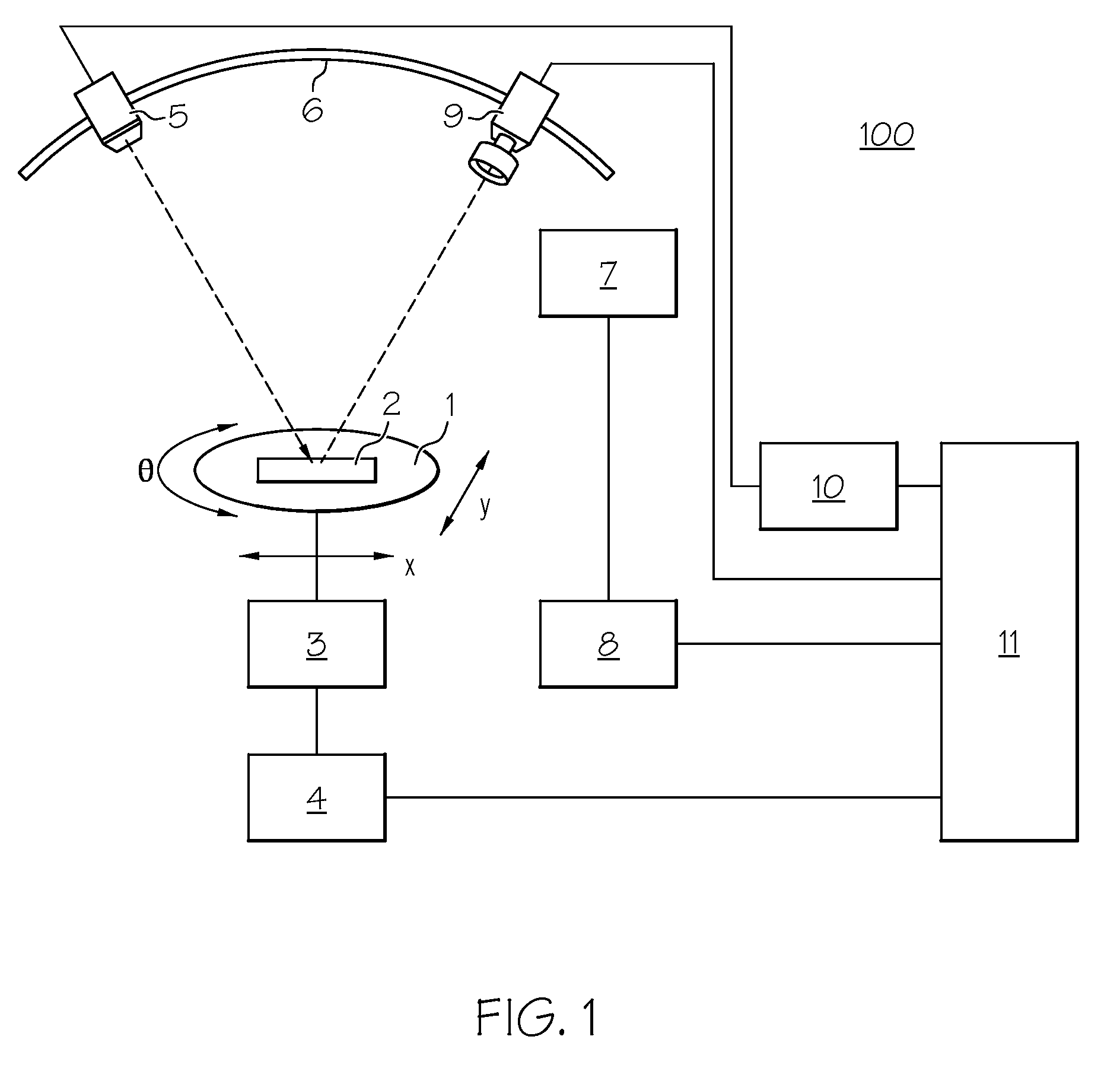
[0013]FIG. 1 is a view illustrating a macro inspection apparatus 100 according to an embodiment of the present invention. Referring to FIG. 1, an inspection object 2 is placed on a stage 1 of a circular shape. The stage 1 is rotated (θ) or moved in a horizontal (x) direction or a vertical (y) direction by a linear motor 3 under control of a stage controller 4. The light source 5 is moved along a rail 6 of an arc shape by a stepping motor 7 under control of a controller 8. The angle of the light source 5 is arbitrarily set relative to the upper surface of the inspection object 2 placed on the stage 1. The brightness of the light source is varied by a power supply 10 for light source. A line sensor camera 9 is moved, similarly to the light source 5, along the arc shaped rail 6 by the stepping motor 7 under control of the controller 8. The output of the line sensor camera 9 is inputted to an image processing unit 11. The image processing unit 11 controls the stage controller 4, control...


PUM

PropertyMeasurementUnit
sizeaaaaaaaaaa
sizeaaaaaaaaaa
lengthaaaaaaaaaa

Abstract

The invention provides a macro inspection apparatus including: a stage on which an inspection object is placed; a light source that irradiates light on an upper surface of the inspection object from an angular direction arbitrarily selected relative to the upper surface of the inspection object; and a line sensor which is placed in an angular direction selected relative to the upper surface of the inspection object so that an optical axis thereof corresponds with an edge of the upper surface area irradiated by the light source and which receives reflected light from the edge of the upper surface area of the inspection object.

Description

FIELD OF THE INVENTION[0001]The present invention relates to a macro inspection apparatus and method that inspects the surface flatness of an inspection object, and more particularly to a macro inspection apparatus and method that inspects the flatness of a thin film on a substrate.BACKGROUND ART[0002]Inspections conducted in the process of fabricating semiconductor, liquid crystals or the like include a macro inspection. In the macro inspection, typically, a human visually spots a defect (flatness, the presence / absence of a scratch, or the like) on the surface of a fabricated film or the like. The macro inspection is an effective inspection because a defect can be spotted over a wide area all at once under the limitations of visual inspection.[0003]As a macro inspection for inspecting the flatness of a film, i.e., a variation (non-uniformity) in film thickness, there has hitherto been conducted an inspection using interference light. In the inspection using interference light, narr...

Claims


Application Information

Patent Timeline
Patent Type & Authority Patents(United States)
IPC IPC(8): G01N21/88
CPCG01N21/8422G01N21/8806G01N21/9501
Inventor KOHAYASE, ATSUSHIUDA, MITSURU
Owner INT BUSINESS MASCH CORP
Why Eureka
Try Eureka