Process cartridge

a technology of process cartridges and processing rollers, applied in the field of process cartridges, can solve the problems of permanent deformation of the elastic layer of the developing roller, uneven image formation, etc., and achieve the effect of increasing the burden on the user

Inactive Publication Date: 2010-05-18
CANON KK
View PDF12 Cites 35 Cited by
  • Summary
  • Abstract
  • Description
  • Claims
  • Application Information

AI Technical Summary

Benefits of technology

[0012]The present invention provides a process cartridge and an image forming apparatus that are improvements of the above-described inventions. That is, according to the present invention, before use, a charging member can be separated from an electrophotographic photosensitive member, and in use, the separation state of the charging member can be released without an increase in the burden on a user.

Problems solved by technology

In the case of this method, when the process cartridge is not used for a long time period in the state of being mounted on the image forming apparatus main body, there is a possibility that an elastic layer of the developing roller is permanently deformed.
Therefore, an uneven image may be formed at the time of development.

Method used


Image

  • Process cartridge
  • Process cartridge
  • Process cartridge

Examples


first embodiment

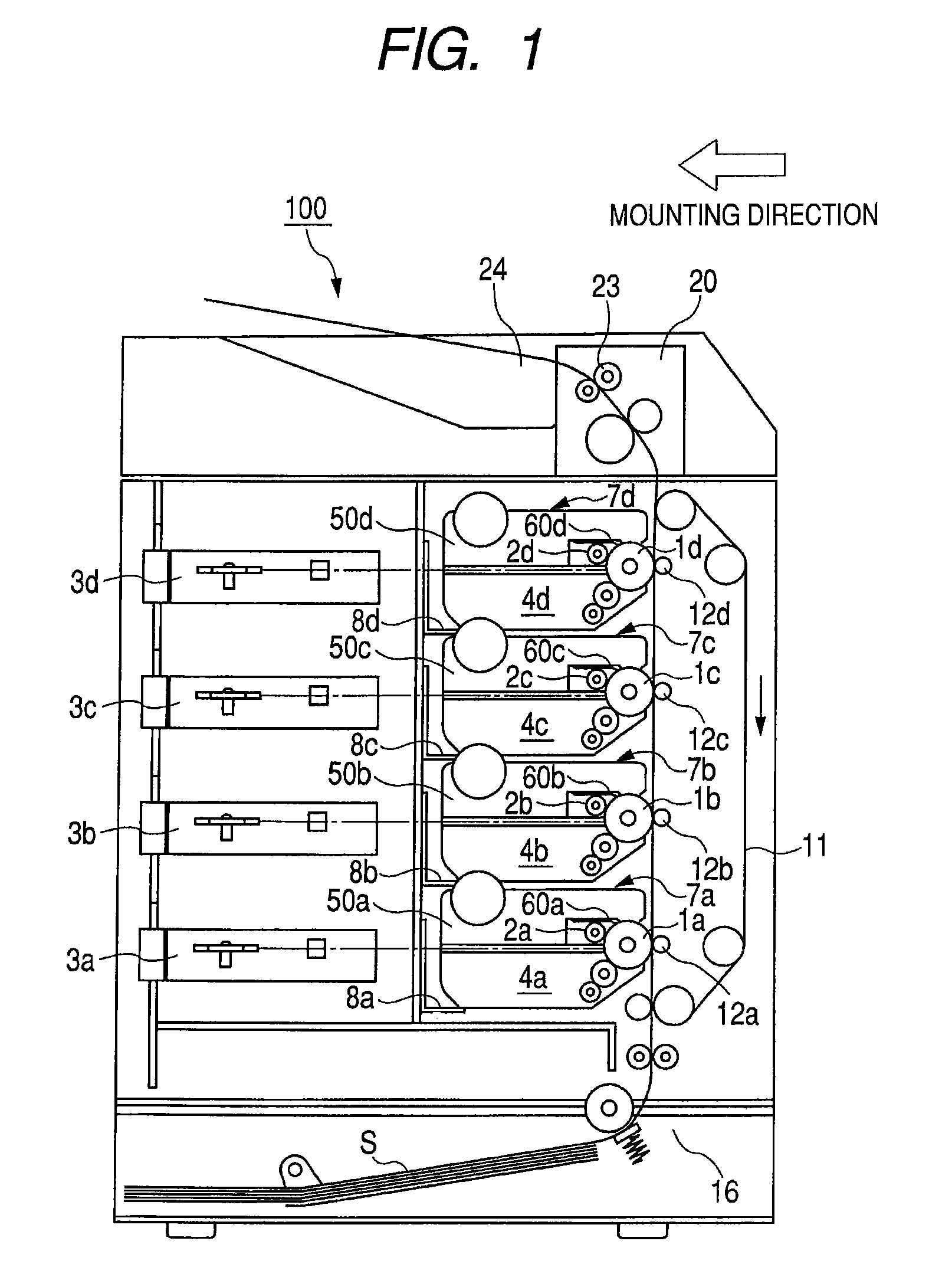
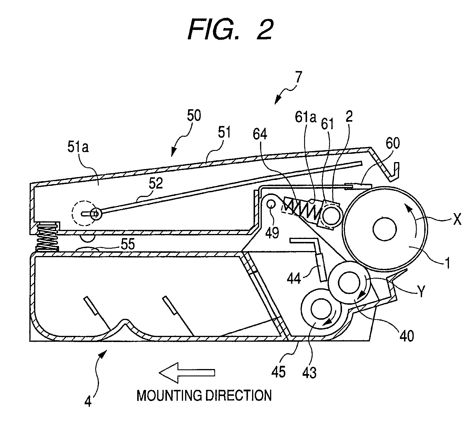
[0036]A first exemplary embodiment of a process cartridge and an image forming apparatus according to the present invention will be described referring to the drawings. FIG. 1 is an overall schematic view of a color electrophotographic image forming apparatus according to this embodiment. FIG. 2 is a sectional explanatory view of a process cartridge. FIG. 3 is a perspective view illustrating a connection construction of the process cartridge.

[0037](Overall Construction of an Image Forming Apparatus)

[0038]First, the overall construction of the image forming apparatus will be described with reference to FIGS. 1 and 2. As illustrated in FIG. 1, an image forming apparatus main body 100 includes four process cartridge mounting portions (8a, 8b, 8c, and 8d) arranged side-by-side in the vertical direction.

[0039]A cartridge 7 (7a, 7b, 7c, 7d) that is mounted at each mounting portion includes a photosensitive drum (electrophotograpic photosensitive member) 1 (1a, 1b, 1c, 1d), being an image ...

second embodiment

[0101]Now, a second embodiment of a process cartridge and an image forming apparatus according to the present invention will be described referring to the drawings. FIG. 13 is a schematic side view of a separation member according to this embodiment. Portions which description is a duplication of that of the above-mentioned first embodiment will be designated with like reference numerals to omit descriptions thereof.

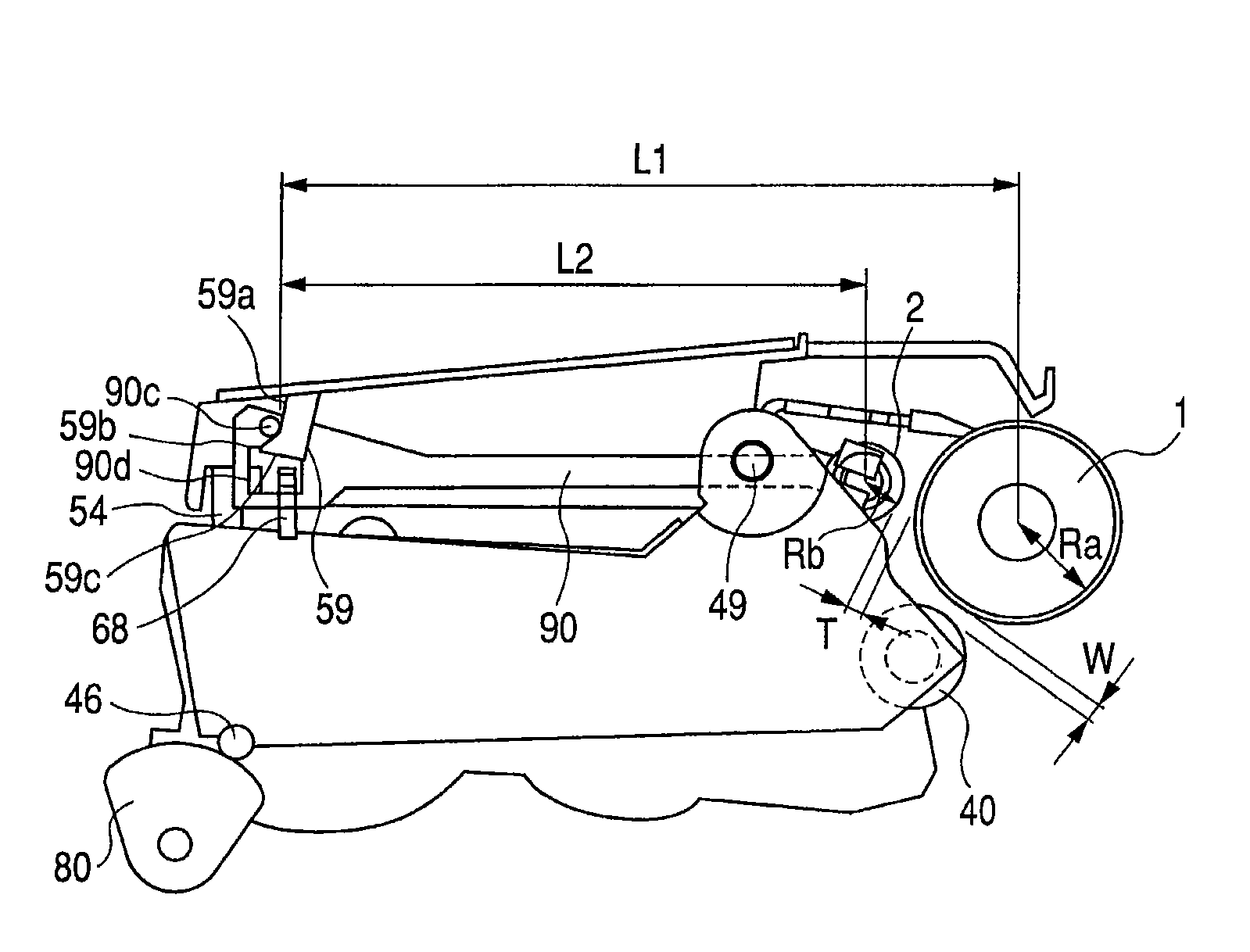
[0102]As illustrated in FIG. 13, in the process cartridge and the image forming apparatus according to this embodiment, there are provided a charging roller separation member 190 and hook portions 159, 168 instead of the separation member 90 and the hook portions 59, 68 according to the above-mentioned first embodiment.

[0103]In the separation member 190, the protrusion 90c and the release hole 90d of the separation member 90 are inverted in position. That is, on the underside of the photosensitive member frame 51, the hook portion 168 is hung down. In addition, on the to...

third embodiment

[0106]Now, a third embodiment of a process cartridge and an image forming apparatus according to the present invention will be described referring to the drawings. FIGS. 14A and 14B are schematic side views of a charging roller separation member according to this embodiment. Portions of the description which duplicate that of the above-mentioned first embodiment will be designated with like reference numerals to omit descriptions thereof.

[0107]As illustrated in FIGS. 14A and 14B, the process cartridge and the image forming apparatus according to this embodiment are provided with a charging roller separation member 290 instead of the separation member 90 according to the above-mentioned first embodiment.

[0108]As illustrated in FIG. 15A, the separation member 290 is provided with a shaft holding portion 290a of an elongated hole shape of elongating the shaft holding portion 90a of the separation member 90 in the separation direction (in the direction indicated by an arrow M) opposite ...


PUM


Abstract

A process cartridge in which before use, the separation of a predetermined distance between a charging roller and a photosensitive drum can be maintained, and in use, the separation state of the charging roller can be released without increasing the burden on a user. The process cartridge includes a charging roller separation member moveable between the first position to hold the separation of the charging roller from the photosensitive drum and the second position to abut the charging roller on the photosensitive drum. One of a photosensitive member unit and a developing unit includes a hook portion holding the separation member in the first position, and the other includes a hook portion that releases the separation member from the hook portion to move the separation member to the second position when the developing unit is pivoted.

Description

BACKGROUND OF THE INVENTION[0001]1. Field of the Invention[0002]The present invention relates to a process cartridge detachably mountable to an electrophotographic image forming apparatus such as an electrophotographic copying machine and an electrophotographic printer.[0003]Here, the electrophotographic image forming apparatus forms an image on a recording sheet using an electrophotographic image forming method, and examples of the electrophotographic image forming apparatus include an electrophotographic copying machine, an electrophotographic printer (for example, a laser beam printer and an LED printer), a facsimile machine and a word processor.[0004]Furthermore, a process cartridge is a cartridge into which at least one of a charging member, a developing unit and a cleaning unit, and an electrophotographic photosensitive member are integrally incorporated, the cartridge being detachably mountable to a main body of an image forming apparatus.[0005]2. Description of the Related A...

Claims


Application Information

Patent Timeline
Patent Type & Authority Patents(United States)
IPC IPC(8): G03G21/18
CPCG03G21/1825G03G21/1821
Inventor ANAN, OSAMUHIRAYAMA, AKINOBU
Owner CANON KK
Why Eureka
Try Eureka