Small thin film-movable element, small thin film-movable element array and image forming apparatus

a technology of small filmmovable elements and arrays, which is applied in the direction of device details, instruments, and piezoelectric/electrostrictive device details, etc., can solve the problems of limiting the speed of switching the optical switch, limiting the range of vibration control methods, and reducing the efficiency of the movable portion, so as to achieve active reduction of vibration and the effect of reducing the drive cycl

Inactive Publication Date: 2007-01-11
FUJIFILM CORP +1
View PDF9 Cites 40 Cited by
  • Summary
  • Abstract
  • Description
  • Claims
  • Application Information

AI Technical Summary

Benefits of technology

[0051] According to the image forming apparatus, by providing the small thin film-movable element array according to any one of (13) to (15) at a main portion of the constitution, vibration can actively be reduced and in comparison with the apparatus of the background art, a drive cycle (switching operation) is shortened.
[0052] According to a small thin film-movable element according to an aspect of the invention, there is provided the second drive source different from the first drive source for increasing and reducing the absolute value of the physical acting force to restrain the vibration of the movable portion in driving to displace the movable portion in the first direction by the first drive source and therefore, the vibration of the movable portion can actively be reduced by operating the physical acting force in the direction reverse to the transition direction of the movable portion and decelerating the movable portion immediately before being brought into contact with the stopping member. As a result, the switching operation of the small thin film-movable element can be constituted by high speed. Further, since the vibration of the movable portion can be reduced, when the movable portion modulates light, vibration of emitted light can be reduced. Further, since the second drive source different from the first drive source is provided, a pattern of the physical acting force applied for controlling the vibration can be constituted by a variety thereof. Further, it is not necessary to superpose a complicated control signal only on the first drive source and therefore, the circuit constitution can be simplified and an increase in a burden of circuit operation can be prevented.
[0053] According to a small thin film-movable element array according to an aspect of the invention are one-dimensionally or two-dimensionally aligned with the small thin film-movable element according to the invention and therefore, the vibration after the movable portion reaches the finally displaced position is restrained, a time period of converging the vibration can be nullified or can considerably be shortened, and the address voltage can be written without needing to await for converging the vibration. Therefore, the switching operation can be constituted by high speed by shortening the drive cycle and high speed operation of a total of the array can be carried out. Further, although high accuracy is requested for an optical switch array for optical communication and therefore, an operational error caused by a variation in the individual elements needs to be corrected, according to the small thin film-movable element array, the operational error can easily be corrected by changing the displacement control signals of the individual small thin film-movable elements in correspondence with the correction.
[0054] According to a small thin film-movable element array according to an aspect of the invention, the image forming apparatus comprises the light source, the small thin film-movable element according to the invention, the illuminating optical system for irradiating light from the light source to the small thin film-movable element array, and the projecting optical system for projecting light emitted from the small thin film-movable element array to the image forming face and therefore, in comparison with the apparatus of the background art, the switching operation can be shortened. As a result, a photosensitive member can be exposed by high speed and by a number of gray scales and a display by a projector by a faster speed can be carried out.

Problems solved by technology

Therefore, until an optical output becomes a constant level by attenuating the vibration, an optical path is not switched and a speed of switching the optical switch is restricted.
The vibration or the overshoot hampers high speed formation in switching operation of the small thin movable element.
However, the small mechanical lattice apparatus is a small thin film-movable element of a so-to-speak parallel flat plate type for displacing the ribbon constituting the movable portion to a side of a board in parallel therewith, a pulse is applied to one movable portion side electrode and one fixed electrode opposed thereto to brake and therefore, there is a disadvantage of being devoid of a variety in the vibration control method.
That is, vibration cannot actively be reduced.
However, although according to the optical switching apparatus, a block constituting the movable portion is bidirectionally being displaced in parallel, the vibration is intended to be restrained by changing the drive force operated in a forward direction and therefore, there is a disadvantage of being devoid of a variety in the vibration control method.
However, according to the control method, an object of control is constituted by reducing a voltage maintained in the pull-in state, reducing ON / OFF delay by discharging residual charge, increasing the amplitudes of the output signal and the like, and vibration cannot actively be reduced.
Further, optical information of laser light or the like is reflected to be incident on a fiber on an emitting side and therefore, a high control accuracy is requested, vibration of the movable portion (mirror portion) constitutes a cause of noise as the above-described chattering.
However, the small electromechanical modulating element is provided with a drawback that an effect of restraining vibration is small since vibration is intended to restrain by noncontact drive.
Particularly, the catch electrode 16 for restraining vibration of the yoke 12 in being operated by a physical acting force is arranged on a plane the same as that of the yoke 12, and is braked by a physical acting force between end faces thereof and therefore, areas of the electrodes opposed to each other are small, a large physical acting force is not achieved and an efficiency of restraining vibration is poor.

Method used


Image

  • Small thin film-movable element, small thin film-movable element array and image forming apparatus
  • Small thin film-movable element, small thin film-movable element array and image forming apparatus
  • Small thin film-movable element, small thin film-movable element array and image forming apparatus

Examples


Embodiment Construction

[0084] A detailed explanation will be given of exempalry embodiments of a small thin film-movable element and a small thin film-movable element array as well as an image forming apparatus according to the invention in reference to the drawings as follows.

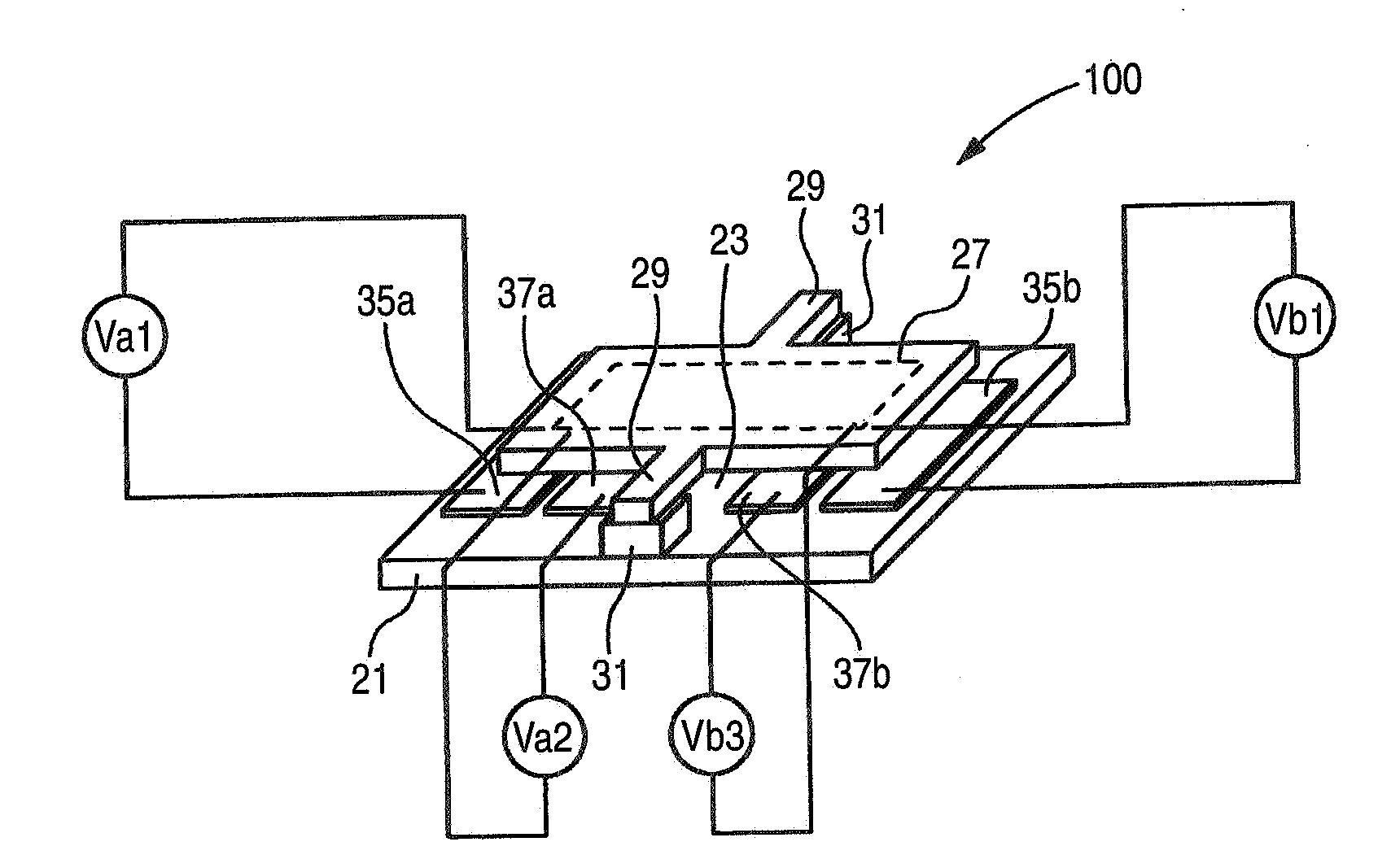
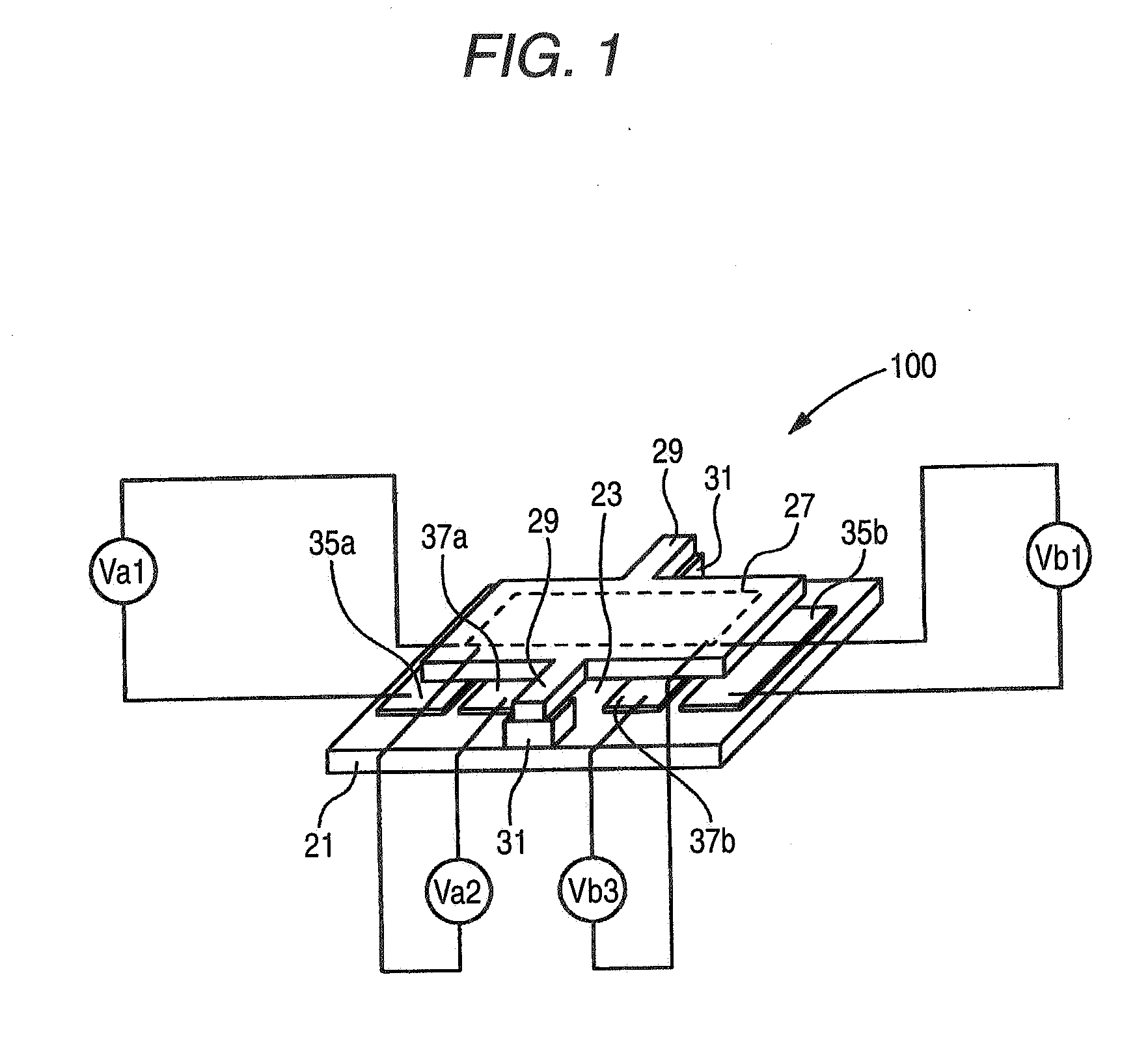
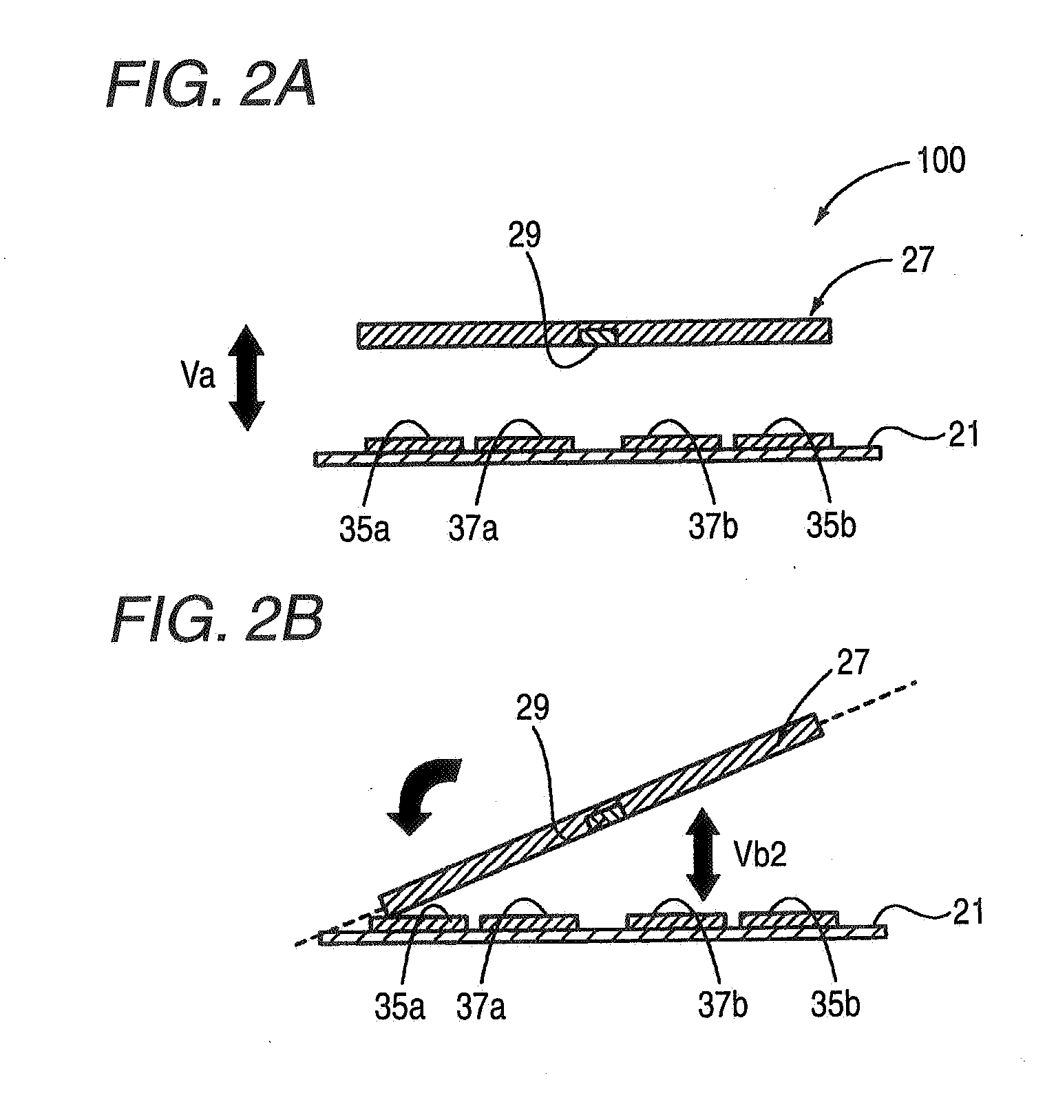
[0085]FIG. 1 is a conceptual view showing a first exemplary embodiment of a small thin film-movable element according to the invention. FIGS. 2A and 2B illustrate explanatory views of operation showing a procedure of pivoting the small thin film-movable element shown in FIG. 1.

[0086] A small thin film-movable element 100 according to the embodiment includes a board 21, a movable portion 27 in a shape of a small piece arranged in parallel with the board 21 by way of a gap 23, hinges 29, 29 constituting support portions extended from both edge portions of the movable portion 27, and spacers 31, 31 for supporting the movable portion 27 by the board 21 by way of the hinges 29, 29 as a basic constitution of a displacement structure. By...


PUM


Abstract

A small thin film-movable element is provided and includes: a movable portion supported elastically deformably and capable of being displaced bidirectionally in one direction and a direction reverse thereto; a first drive source for applying a physical acting force to the movable portion, in which the movable portion produces a modulating or switching function by the first drive source; and a second drive source, which is different from the first drive source, for increasing or reducing an absolute value of the physical acting force to restrain a vibration of the movable portion in driving to displace the movable portion in a first direction by the first drive source.

Description

FIELD OF THE INVENTION [0001] The present invention relates to a small thin film-movable element and a small thin film-movable element array as well as an image forming apparatus preferably used in, for example, optical communication, an exposing apparatus, a projector, an optical switch, a scanner, an RF switch, an actuator, a multiplexer and the like. BACKGROUND OF THE INVENTION [0002] In recent years, by rapid progress of an MEMS technology (Micro-Electro Mechanical systems), a development of a small thin film-movable element for electrically displacing or moving a small thin film of μm order has intensively been carried out. As the small thin film-movable element, there is, for example, a digital micromirror device (DMD) for deflecting light by inclining a micromirror, an optical switch for switching an optical path or the like. DMD has a wide use in a field of an optical information processing such as a projecting display, a video monitor, a graphic monitor, a television set an...

Claims


Application Information

Patent Timeline
Patent Type & Authority Applications(United States)
IPC IPC(8): H01L41/04G02B26/08
CPCG02B26/0841H02N1/006G02B26/0858G02B26/085
Inventor OGIKUBO, SHINYANAKAMURA, HIROCHIKA
Owner FUJIFILM CORP
Why Eureka
Try Eureka