Endoscopic surgery device and outer tube

a surgery device and endoscope technology, applied in the field of endoscope surgery devices and outer tubes, can solve the problems of increasing the burden on the body, enlarging the system, and affecting the operation of the endoscope, so as to facilitate treatment, improve the operability of the endoscope, and facilitate the operation

Active Publication Date: 2015-03-19
FUJIFILM CORP
View PDF5 Cites 43 Cited by
  • Summary
  • Abstract
  • Description
  • Claims
  • Application Information

AI Technical Summary

Benefits of technology

[0011]In addition, in a method of operating a bending portion of an endoscope by tilting operation of a treatment tool, as described in PTL 2, there is a problem in which it is required to enlarge an incision range of a portion into which the endoscope is to be inserted so that the treatment tool can be tilted with respect to the endoscope, thereby increasing a burden to a body.
[0094]According to the present invention, an object of the present invention is to provide an endoscopic surgery device and an outer tube, capable of easily obtaining an image desired by an operator to facilitate treatment as well as of performing minimally invasive surgery.

Problems solved by technology

Unfortunately, there is a problem in which, if an operation range of a treatment tool is regulated by detecting an observation state of the endoscope as described in PTL 1, an originally possible movement is limited to cause treatment to conversely become difficult.
In addition, since the operation range of the treatment tool is regulated by detecting the observation state of the endoscope, there is a drawback of enlarging the system.
In addition, in a method of operating a bending portion of an endoscope by tilting operation of a treatment tool, as described in PTL 2, there is a problem in which it is required to enlarge an incision range of a portion into which the endoscope is to be inserted so that the treatment tool can be tilted with respect to the endoscope, thereby increasing a burden to a body.

Method used


Image

  • Endoscopic surgery device and outer tube
  • Endoscopic surgery device and outer tube
  • Endoscopic surgery device and outer tube

Examples


first embodiment

Configuration

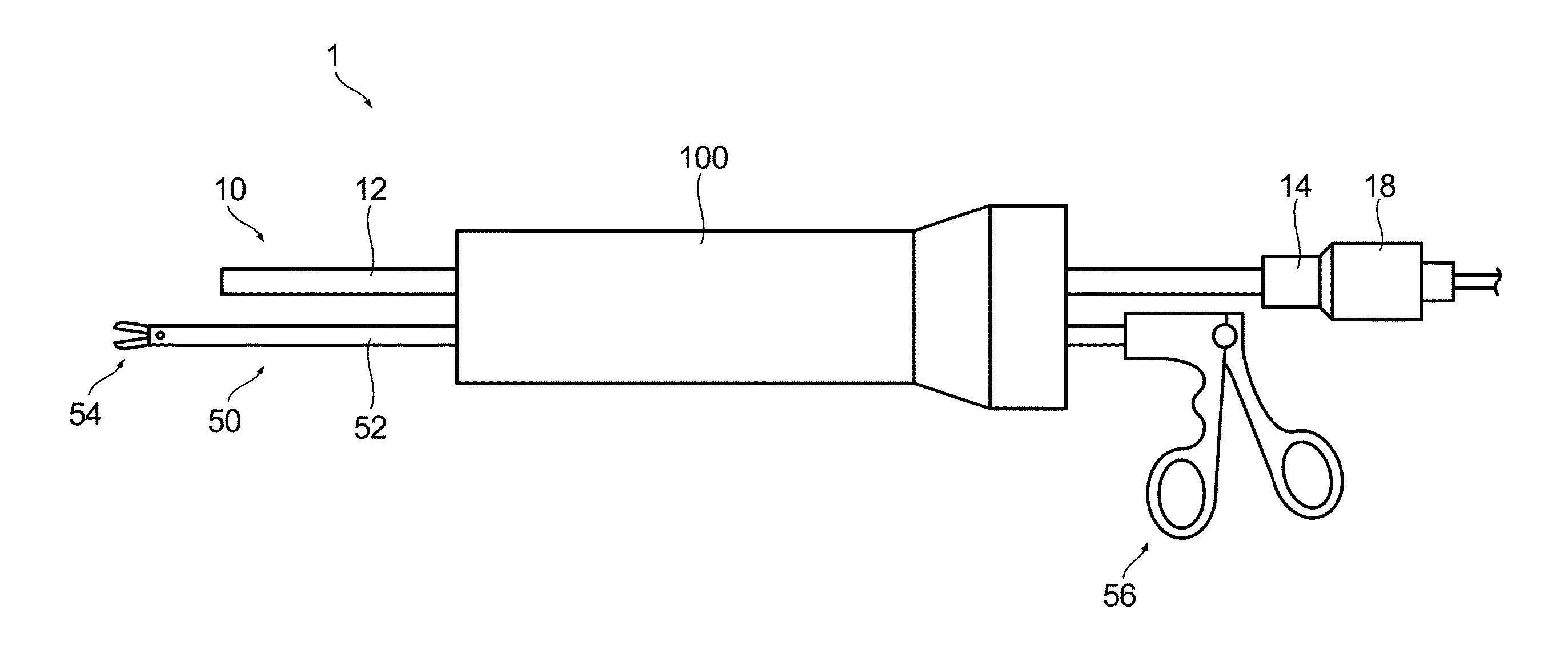
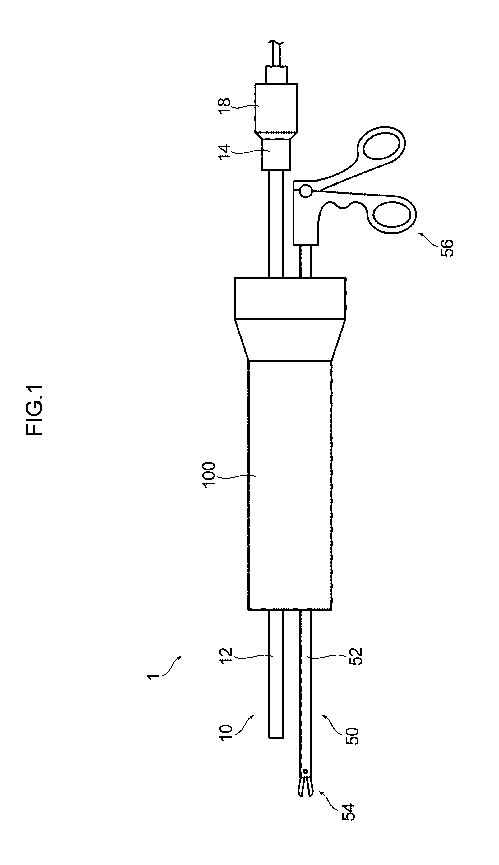
[0130]FIG. 1 is a schematic configuration diagram of a first embodiment of the endoscopic surgery device in accordance with the present invention.

[0131]As shown in FIG. 1, an endoscopic surgery device 1 of the first embodiment includes: an endoscope 10 that is to be inserted into a body cavity of a patient to observe inside the body cavity; a treatment tool 50 that is to be inserted into the body cavity of the patient to perform required treatment; and an outer tube (trocar) 100 that guides the endoscope 10 and the treatment tool 50 into the body cavity of the patient.

(Endoscope)

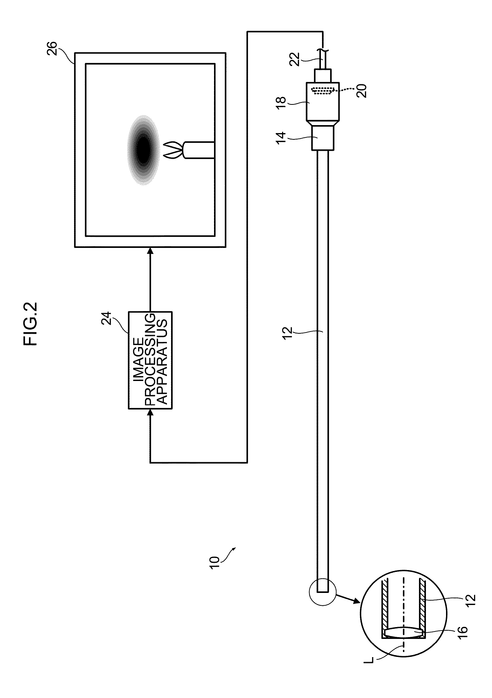
[0132]FIG. 2 is a schematic configuration diagram showing an example of an endoscope.

[0133]The endoscope 10 is, for example, composed of a rigid endoscope of a direct viewing type, such as a laparoscope. The endoscope 10 includes a linear insertion section 12 that is to be inserted into a body cavity of a patient, and an eyepiece part 14 that is provided at a proximal end part of the insertion s...

second embodiment

Configuration

[0201]FIG. 10 is a schematic configuration diagram of a main section of a second embodiment of the endoscopic surgery device in accordance with the present invention.

[0202]As shown in FIG. 10, the endoscopic surgery device of the second embodiment is different from the endoscopic surgery device of the first embodiment described above in a part of the configuration of the outer tube 100. Thus, hereinafter only the different part will be described.

[0203]The outer tube 100 of the endoscopic surgery device of the second embodiment is configured to have a “play” in interlock between the endoscope 10 and the treatment tool 50. Specifically, the treatment tool 50 is provided so as to be movable with respect to the slider 118 with a predetermined stroke.

[0204]As shown in FIG. 10, the slider 118 is provided with a treatment tool holding section 124 for holding the treatment tool 50.

[0205]The treatment tool holding section 124 includes: a treatment tool holding hole 128 into whic...

third embodiment

Configuration

[0232]FIG. 12 is a schematic configuration diagram of a main section of a third embodiment of the endoscopic surgery device in accordance with the present invention.

[0233]The endoscopic surgery device of the third embodiment is different from the endoscopic surgery device of the second embodiment described above in that the endoscopic surgery device of the third embodiment includes a lock mechanism for locking the endoscope 10 inserted into the outer tube 100 at a predetermined position with respect to the slider 118. Thus, hereinafter only the lock mechanism for the endoscope 10, which is the different portion, will be described.

[0234]The lock mechanism for locking the endoscope 10 fixes the insertion section 12 of the endoscope 10 inserted into the outer tube 100 at the predetermined position with respect to the slider 118.

[0235]The lock mechanism for locking the endoscope 10 is provided in the endoscope holding hole 132, and is composed of: an endoscope lock pin 152 ...


PUM


Abstract

An object of the present invention is to provide an endoscopic surgery device and an outer tube, capable of easily obtaining an image desired by an operator to facilitate treatment as well as of performing minimally invasive surgery. In the endoscopic surgery device and the outer tube, an endoscope and a treatment tool are inserted into a body cavity through an outer tube. The outer tube is provided with a built-in slider. The slider is provided so as to be axially movable in the outer tube body. The endoscope and the treatment tool, inserted into the outer tube, are held by the slider. Moving the treatment tool allows endoscope to be moved in conjunction with the movement of the treatment tool.

Description

CROSS-REFERENCE TO RELATED APPLICATIONS[0001]This application is a Continuation of PCT International Application No. PCT / JP2013 / 064183 filed on May 22, 2013, which claims priority under 35 U.S.C §119(a) to Japanese Patent Application No. 2012-120319 filed on May 25, 2012. Each of the above applications is hereby expressly incorporated by reference, in their entirety, into the present application.BACKGROUND OF THE INVENTION[0002]1. Field of the Invention[0003]The present invention relates to an endoscopic surgery device and an outer tube, and more particularly to an endoscopic surgery device and an outer tube that are configured to interlock an endoscope with a treatment tool.[0004]2. Description of the Related Art[0005]There is known a laparoscope as an endoscope instrument that is to be inserted into an abdominal cavity through body surface skin. In recent years, an operation using the laparoscope (laparoscopic surgery) has become widespread in many operations because an operative ...

Claims


Application Information

Patent Timeline
Patent Type & Authority Applications(United States)
IPC IPC(8): A61B17/34A61B17/00A61B1/00
CPCA61B17/3423A61B1/00154A61B2017/347A61B2017/3445A61B17/00234A61B1/00135A61B1/0014A61B1/042A61B1/3132A61B17/3421A61B17/3462A61B2017/3441A61B1/00147
Inventor DEJIMA, TAKUMITORISAWA, NOBUYUKI
Owner FUJIFILM CORP
Why Eureka
Try Eureka