
Sprung gear set and method

a gear set and gear technology, applied in the direction of gearing, gearing details, hoisting equipment, etc., can solve the problems of increasing objectionable noise, increasing backlash, and increasing backlash

Inactive Publication Date: 2010-05-25
STEERING SOLUTIONS IP HLDG +1
View PDF83 Cites 27 Cited by
  • Summary
  • Abstract
  • Description
  • Claims
  • Application Information

AI Technical Summary

Benefits of technology

The patent describes an apparatus and method for meshing gears. The apparatus includes a housing, first and second gears, and a biasing member that pushes the first gear towards the second gear. The apparatus also includes a constraint that keeps the first gear in a plane with a perpendicular line and the second gear. The method involves urging the first gear into mesh with the second gear and keeping the first gear in a plane with the second gear. The technical effect of this invention is to ensure continuous contact of the teeth of the gears and reduce friction between them.

Problems solved by technology

Much of the backlash is due to dimensional variations of the various components that make up the gear system.
Additional backlash is created due to normal wear of components over time.
As a result, the objectionable noise tends to increase as the parts wear and the clearances increase.
While gear play noise is not indicative of a defect in the gearing system, it often proves to be an annoyance and it is desirable to minimize it as much as practicable.

Method used


Image

  • Sprung gear set and method
  • Sprung gear set and method
  • Sprung gear set and method

Examples


Embodiment Construction

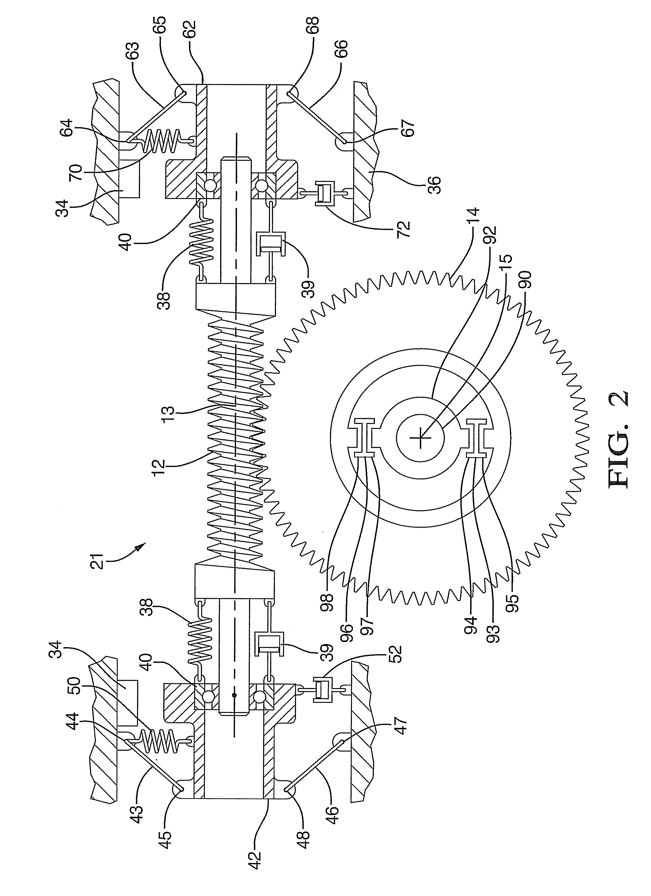
[0026]A detailed description of several embodiments of the disclosed apparatus and method are presented herein by way of exemplification and not limitation with reference to FIGS. 1 through 4.

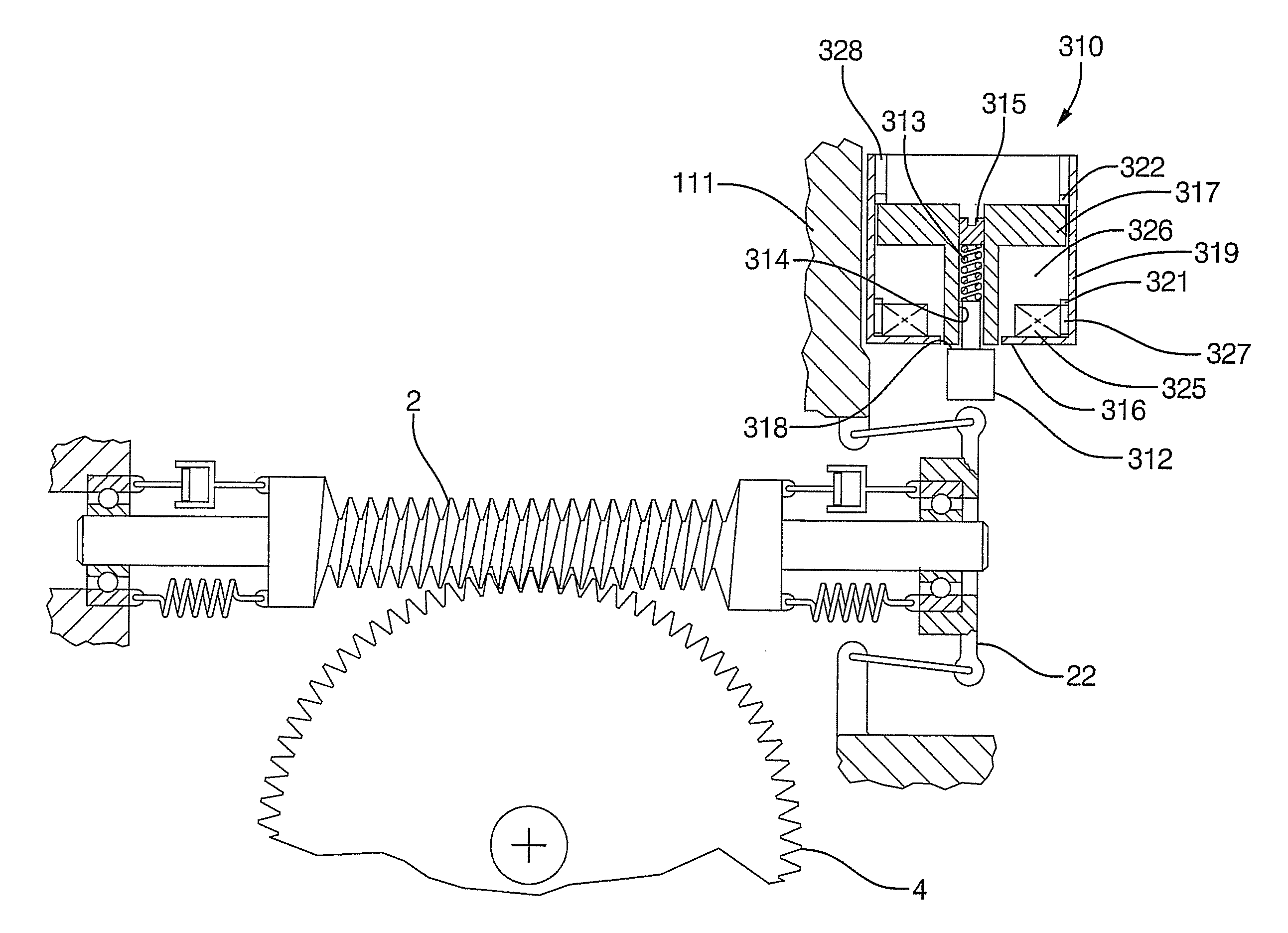
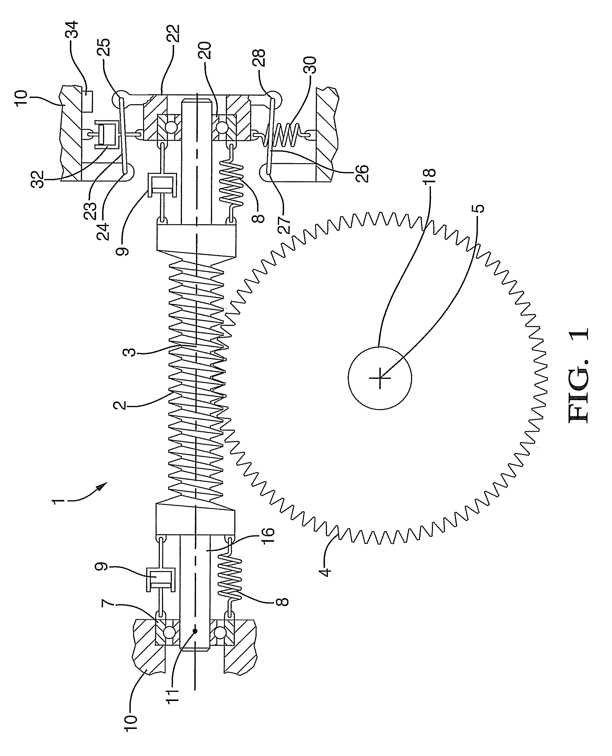
[0027]A schematic representation of the gear set apparatus 1 of one embodiment of the present invention is depicted in FIG. 1. A cross-axis gear set with, a first gear, worm 2 and a second gear, worm gear 4 are shown meshed together such that worm gear axis 5 and worm axis 3 form a 90 degree angle between the two gear axes when viewed along the direction of a line that is commonly perpendicular to each axis. Accordingly, rotation of worm 2 about worm axis 3 causes worm gear 4 to rotate about worm gear axis 5.

[0028]Both the worm 2 and the meshed worm gear 4 are located within a housing 10. The worm gear 4 and the axis 5 are held positionally constant relative to the housing 10, whereas, the worm 2 and the axis 3 are repositionable relative to the housing 10. The movement of the worm 2 and the ax...


PUM


Abstract

Disclosed herein is an apparatus that relates to a gear set. The apparatus includes, a housing, a first gear movable in the housing such that a first axis defined by the first gear is repositionable relative to the housing, a second gear in mesh with the first gear, and a second axis defined by the second gear. The apparatus constrains movement of the first axis to a plane containing both the first axis and a line commonly perpendicular to the first axis and the second axis, and a biasing member that urges the first gear toward the second gear.

Description

CROSS REFERENCE TO RELATED APPLICATION[0001]This application claims priority to U.S. provisional application 60 / 742,449, filed Dec. 5, 2005, the entire contents of which are incorporated herein by reference.BACKGROUND OF THE INVENTION[0002]Gear sets are useful devices for transmitting torque, and changing the direction of motion as well as changing the ratio of an input motion to that of an output motion. Clearance between the teeth of one gear and the teeth of a meshing gear is often referred to as backlash. At times, backlash may manifest itself as perceptible noise attributable to rattling of gear teeth as the teeth from one gear make contact with the teeth of a mating gear. The loudness and the annoyance associated with it are proportional to the amount of backlash present.[0003]A certain amount of backlash is required and is intentionally built into gear systems to prevent energy loss due to friction. Much of the backlash is due to dimensional variations of the various componen...

Claims


Application Information

Patent Timeline
Patent Type & Authority Patents(United States)
IPC IPC(8): F16H3/34F16H1/16F16H55/18F16H57/12
CPCF16H1/16F16H55/24F16H57/0006F16H2057/0225F16H2057/0213Y10T74/19828Y10T74/1955Y10T74/1966Y10T74/19358Y10T74/19623Y10T74/19284F16F15/022
Inventor AUGUSTINE, MICHAEL J.ROSS, CHRISTIAN E.COLLIER-HALLMAN, STEVEN J.ISLAM, MOHAMMAD S.
Owner STEERING SOLUTIONS IP HLDG
Learn More