Variable valve mechanism for internal combustion engine

a valve mechanism and internal combustion engine technology, applied in valve drives, valve drives, machines/engines, etc., can solve problems such as lock-up or damage of worm gear mechanisms, actuators can be rotated to exceed limits,

Inactive Publication Date: 2010-05-25
TOYOTA JIDOSHA KK
View PDF12 Cites 12 Cited by
  • Summary
  • Abstract
  • Description
  • Claims
  • Application Information

AI Technical Summary

Benefits of technology

[0008]The present invention addresses these problems discussed above and it is an object of the present invention to provide, for a variable valve mechanism that has a control shaft operating a variable mechanism connected via a worm gear mechanism to an actuator rotatably driving the control shaft, a structure that can prevent the worm gear mechanism from being locked up or damaged by an excessive rotation of the actuator and the variable valve mechanism from being damaged by an excessive rotation of the control shaft.
[0028]According to the tenth aspect of the present invention, the teeth of the worm wheel remain engaged with the worm gear even when the worm wheel and the worm gear are brought out of mesh with each other. By rotating the worm gear in the opposite direction, therefore, the worm wheel and the worm gear can be once again brought in mesh with each other. This allows the control shaft to be rotated again via the worm gear mechanism, making it possible to resume the operation of the element to be driven quickly.

Problems solved by technology

In the aforementioned known variable valve mechanism, however, the actuator can be rotated to exceed a limit amount because of a system failure or the like.
Consequently, a screw-in action of the worm gear has causes the worm gear to be in excessive mesh with the worm wheel, resulting at times in a locked-up or damaged worm gear mechanism.

Method used


Image

  • Variable valve mechanism for internal combustion engine
  • Variable valve mechanism for internal combustion engine
  • Variable valve mechanism for internal combustion engine

Examples


first embodiment

[0040]A first embodiment of the present invention will be described below with reference to FIGS. 1 through 7B.

General Structure of the Variable Valve Mechanism According to this Embodiment

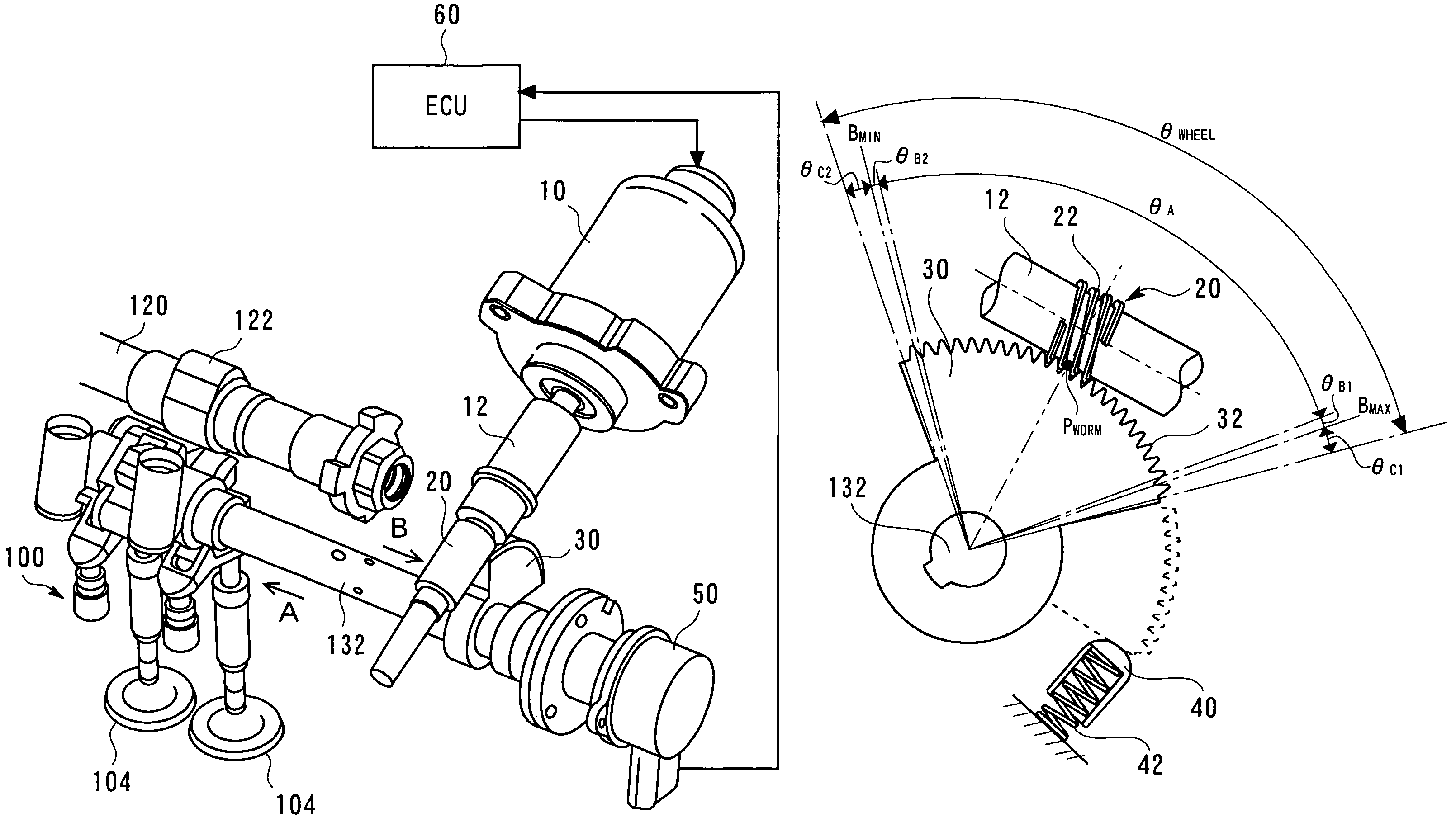
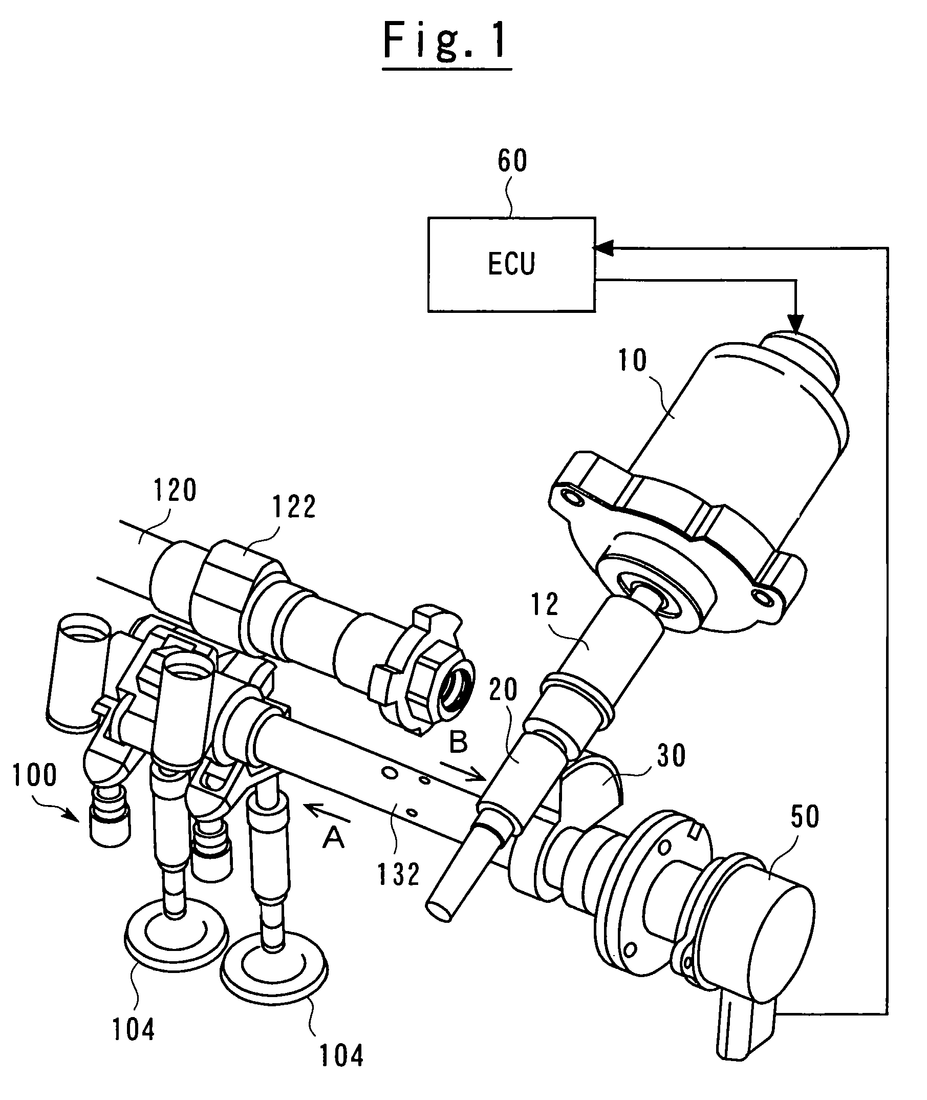
[0041]FIG. 1 is a perspective view showing a general structure of a variable valve mechanism according to the first embodiment of the present invention. Referring to FIG. 1, a variable valve mechanism 100 according to the embodiment of the present invention is interposed between a camshaft 120 and intake valves 104. The variable valve mechanism 100 operatively couples a rotational movement of a cam 122 to a vertical movement of the intake valves 104. The variable valve mechanism 100 includes a control shaft 132 that is disposed in parallel with the camshaft 120. Varying an angular position of the control shaft 132 allows an operative coupling condition to be changed between the rotational movement of the cam 122 and the vertical movement of the intake valves 104, which, in turn, varies an acting a...

second embodiment

[0081]A second embodiment of the present invention will be described below with reference to FIGS. 7A, 7B, and 8.

[0082]A variable valve mechanism according to the second embodiment of the present invention is characterized in that an arrangement for correcting deviation of a signal from a lift sensor 50 is newly added to the basic structure of the arrangements according to the first embodiment of the present invention. In each of FIGS. 7A, 7B, and 8, like reference numerals refer to like parts and duplicate descriptions will be omitted or simplified.

[0083]FIG. 7A is a view showing a worm gear mechanism according to the second embodiment of the present invention as viewed from the direction of arrow B of FIG. 1. FIG. 7A corresponds to FIG. 5 according to the first embodiment of the present invention. Referring to FIG. 7A, a shock absorber 40 includes a lever 44 newly added thereto. The lever 44 is fixed to the shock absorber 40. When a worm wheel 30 abuts on the shock absorber 40, th...

third embodiment

[0090]A third embodiment of the present invention will be described below with reference to FIG. 9.

[0091]A variable valve mechanism according to the third embodiment of the present invention is characterized in that the mechanism allows deviation of a signal of a lift sensor 50 to be corrected without adding any new arrangement to the structure of the arrangements according to the first embodiment of the present invention.

[0092]FIG. 9 is a diagram showing changes in the magnitude of a supply current fed to a motor 10 and changes in the signal from the lift sensor 50 relative to the angular position of a worm wheel 30. Angular positions A, B, and C indicated on the abscissa of FIG. 9 correspond, respectively, to the angular positions A, B, and C of the worm wheel 30 exemplified in the second embodiment of the present invention. Referring to FIG. 9, the motor supply current decreases gradually as the angular position of the worm wheel 30 changes toward the small lift side. This is bec...


PUM


Abstract

A worm gear is connected to an actuator and a worm wheel is connected to a control shaft. The worm wheel has teeth formed only on a predetermined angular range thereof. The above-referenced angular range includes a required rotational range of the control shaft. The worm wheel is formed to be brought out of mesh with the worm gear outside the predetermined angular range.

Description

TECHNICAL FIELD[0001]The present invention relates to a variable valve mechanism that allows a maximum lift amount of a valve to be varied using a variable mechanism. More particularly, the present invention relates to a variable valve mechanism that has a control shaft operating a variable mechanism connected via a worm gear mechanism to an actuator rotatably driving the control shaft.BACKGROUND ART[0002]A known variable valve mechanism, as that disclosed, for example, in Japanese Patent Laid-open No. 2000-234507, varies a maximum lift amount and open / close timing of a valve according to an engine operating condition. The variable valve mechanism disclosed in Japanese Patent Laid-open No. 2000-234507 includes a variable mechanism and an actuator. The variable mechanism varies the maximum lift amount and open / close timing of a valve according to an angular position of a control shaft. The actuator controls the angular position of the control shaft. The actuator is connected to the s...

Claims


Application Information

Patent Timeline
Patent Type & Authority Patents(United States)
IPC IPC(8): F01L1/34
CPCF01L13/0021F01L13/0063F01L2013/0068F01L2013/0073F01L2305/00Y10T74/2107
Inventor TATENO, MANABU
Owner TOYOTA JIDOSHA KK
Why Eureka
Try Eureka