Lighting device

a technology of light source and light source, which is applied in the field of light source, can solve the problems of incandescent light bulbs that are very energy-inefficient light sources, fluorescent light bulbs, and are still less efficient as compared to solid-state light emitters, and achieves high cri ra, long life, and favorable reduction of glare

Active Publication Date: 2010-05-25
IDEAL IND LIGHTING LLC
View PDF132 Cites 220 Cited by
  • Summary
  • Abstract
  • Description
  • Claims
  • Application Information

AI Technical Summary

Benefits of technology

[0032]In one preferred aspect of the present invention, there is provided a light fixture which employs solid state light emitters (e.g., LEDs) and which can be mounted in a room (e.g., in a ceiling), where heat from the solid state light emitters is effectively transferred to the room environment, direct view of the solid state light emitters is obscured (to reduce glare), and / or collimation and / or mixing and / or filtering of the light is provided before and / or as it is exiting the fixture into the room.
[0033]In another preferred aspect of the present invention, there is provided a light fixture using solid state light emitters (e.g., LEDs) that is aesthetically attractive and which can be recessed into a ceiling (or other construction surface, e.g., a wall or a floor). In particular embodiments according to the present invention, such lighting fixtures can have favorably reduced glare, can have a “warm” color temperature, can have a high CRI Ra, can have a very long life, can present reduced fire hazard (or negligible fire hazard), can be energy efficient and / or can be easy to install.

Problems solved by technology

It is well-known that incandescent light bulbs are very energy-inefficient light sources—about ninety percent of the electricity they consume is released as heat rather than light.
Fluorescent light bulbs are more efficient than incandescent light bulbs (by a factor of about 10) but are still less efficient as compared to solid state light emitters, such as light emitting diodes.
In addition, as compared to the normal lifetimes of solid state light emitters, e.g., light emitting diodes, incandescent light bulbs have relatively short lifetimes, i.e., typically about 750-1000 hours.
Fluorescent bulbs have longer lifetimes (e.g., 10,000-20,000 hours) than incandescent lights, but provide less favorable color reproduction.
Another issue faced by conventional light fixtures is the need to periodically replace the lighting devices (e.g., light bulbs, etc.).
Such issues are particularly pronounced where access is difficult (e.g., vaulted ceilings, bridges, high buildings, traffic tunnels) and / or where change-out costs are extremely high.
Light-producing device lifetime is typically much shorter, thus creating the need for periodic change-outs.
Although the development of light emitting diodes has in many ways revolutionized the lighting industry, some of the characteristics of light emitting diodes have presented challenges, some of which have not yet been fully met.
As the lamp is mounted in the can, much of the heat generated by the light source is trapped within the can, because the air heated in the can rises and is trapped within the can.
The environment inside the can is not ideal for solid-state lighting.
LEDs, for example, have significant energy and lifetime benefits over incandescent and fluorescent light sources—LEDs, however, do not operate well in high temperatures.
An LED's lifetime is significantly shortened, however, if it operates at elevated temperatures.

Method used


Image

  • Lighting device
  • Lighting device
  • Lighting device

Examples


Embodiment Construction

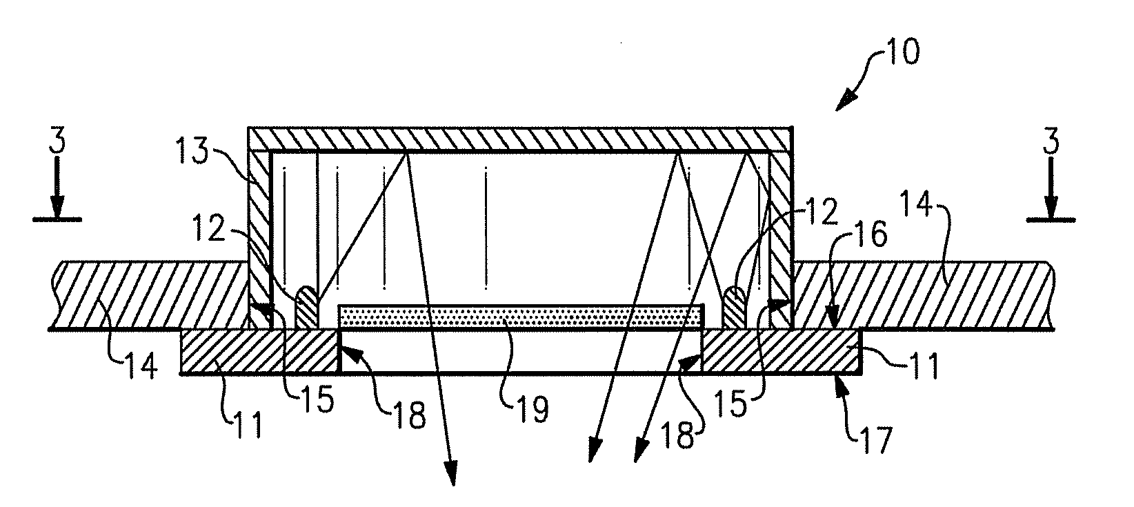
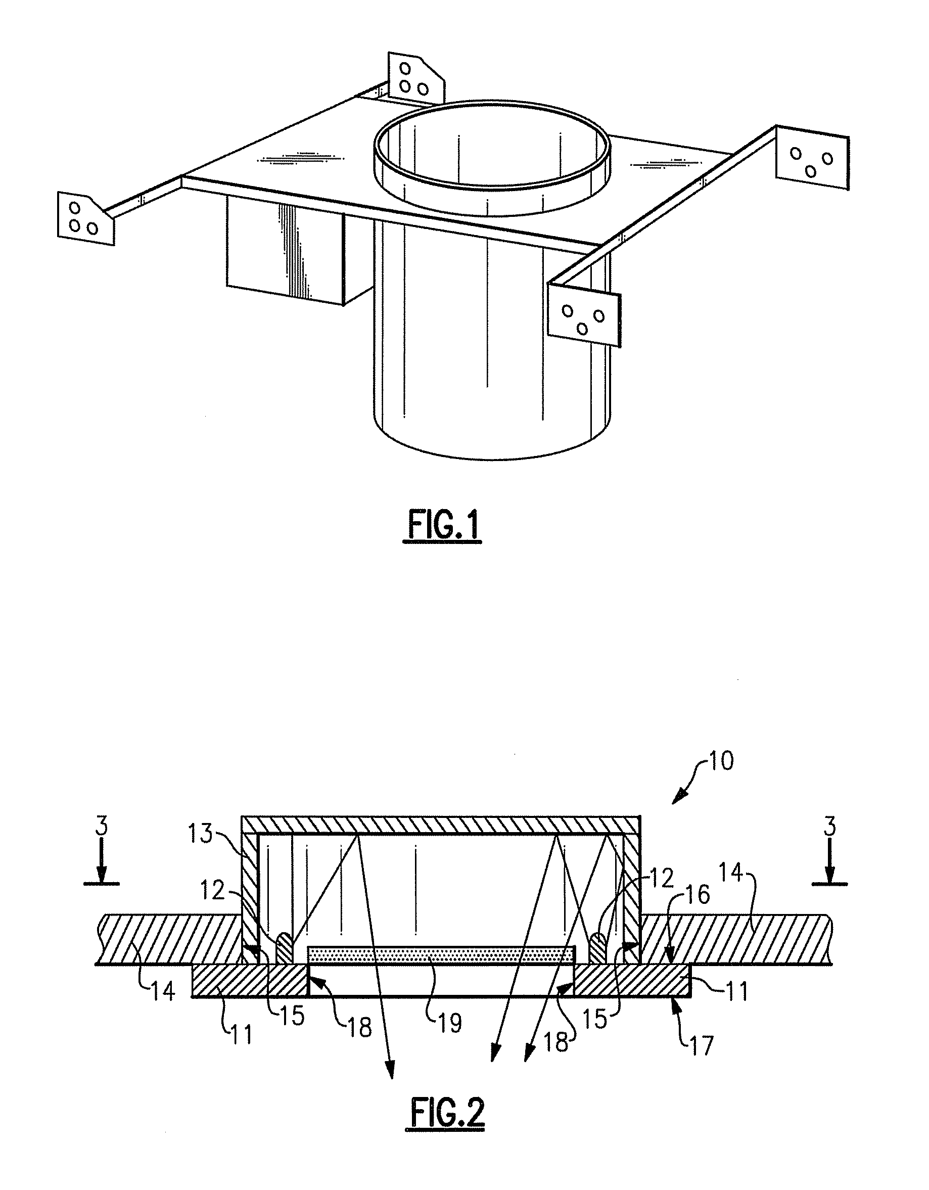
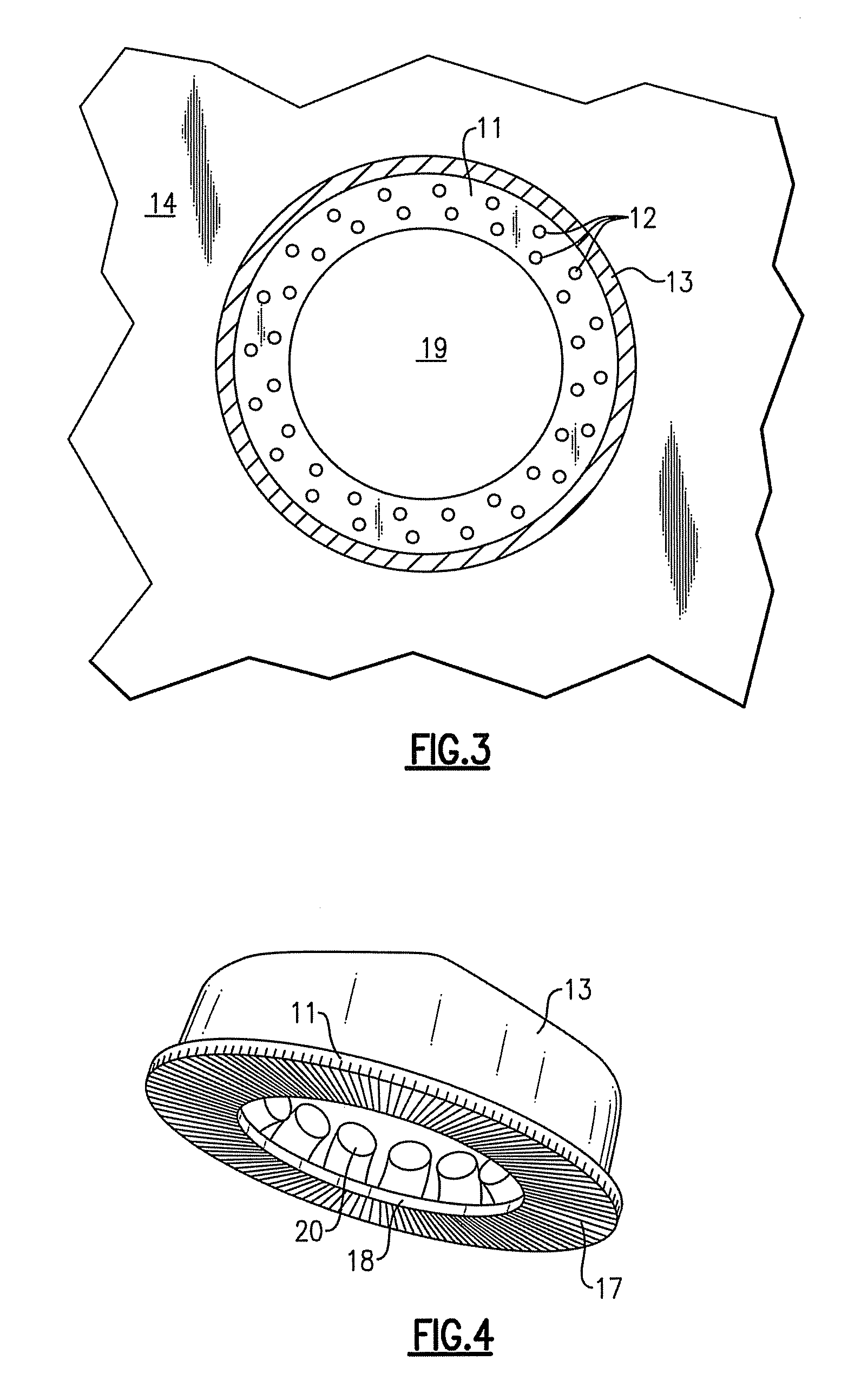
[0051]As noted above, in first, second and third aspects of the present invention, there are provided lighting devices, each comprising at least one thermal conduction element, a plurality of solid state light emitters and at least one reflective element. In a fourth aspect of the present invention, there is provided a lighting device comprising at least one thermal conduction element and a plurality of solid state light emitters.

[0052]The at least one thermal conduction element can be made of any material which provides good heat conduction, as well as other properties needed to function properly in the environment in which it is deployed and in view of its design, e.g., structural rigidity, resistance to abrasion and corrosion, etc. A representative example of a suitable material out of which the thermal conduction element(s) can be constructed is aluminum.

[0053]In some embodiments according to the present invention, the thermal conduction element defines at least one conduction e...


PUM


Abstract

First, second and third lighting devices each comprise a thermal conduction element, solid state light emitters and a reflective element. In the second device, the conduction element defines an opening; and the emitters and reflective element are mounted on a first side of the conduction element. In the third device, the conduction element defines an opening; a first portion of a first side of the conduction element is in contact with a contact region of a construction surface; and the emitters and reflective element are mounted on the first side. A fourth device comprises a conduction element and emitters; a first portion of a first side of the conduction element is in contact with a contact region of a construction surface; the emitters are mounted on a second portion of the first side of the conduction element; and a second side of the conduction element is exposed to ambient air.

Description

CROSS-REFERENCE TO RELATED APPLICATION[0001]This application claims the benefit of U.S. Provisional Patent Application No. 60 / 798,446, filed May 5, 2006, the entirety of which is incorporated herein by reference.FIELD OF THE INVENTION[0002]The present invention relates to a lighting device, in particular, a device which includes one or more solid state light emitters. In a specific aspect, the present invention relates to a “recessed can” lighting device.BACKGROUND OF THE INVENTION[0003]A large proportion (some estimates are as high as twenty-five percent) of the electricity generated in the United States each year goes to lighting. Accordingly, there is an ongoing need to provide lighting which is more energy-efficient. It is well-known that incandescent light bulbs are very energy-inefficient light sources—about ninety percent of the electricity they consume is released as heat rather than light. Fluorescent light bulbs are more efficient than incandescent light bulbs (by a factor...

Claims


Application Information

Patent Timeline
Patent Type & Authority Patents(United States)
IPC IPC(8): F21V29/00F21V29/505
CPCF21V29/2212F21S8/026F21V7/005F21V29/004F21V7/0008F21W2131/101F21Y2101/02F21Y2103/003F21Y2103/022F21S9/032F21V7/22F21V9/08Y10S362/80F21V29/76F21V29/83F21Y2103/10F21Y2103/33F21Y2115/10F21V7/26Y02B20/72F21V15/00
Inventor VAN DE VEN, ANTONY PAUL
Owner IDEAL IND LIGHTING LLC
Why Eureka
Try Eureka