Apparatus for and method of processing a substrate with processing liquid

a technology of substrate and processing liquid, which is applied in the direction of cleaning process and apparatus, chemistry apparatus and processes, cleaning using liquids, etc., can solve the problems of poor precision of etching width, inability to control the amount of liquid flowing over severely limited quantity of etching liquid supplied to the top surface, so as to increase the throughput of the apparatus and increase the processing width

Inactive Publication Date: 2010-05-25
DAINIPPON SCREEN MTG CO LTD
View PDF19 Cites 28 Cited by
  • Summary
  • Abstract
  • Description
  • Claims
  • Application Information

AI Technical Summary

Benefits of technology

[0008]To ensure evenness of the etching width in the top rim portion of the substrate, the approach that can be considered is to supply the processing liquid directly to the top rim portion of the substrate, instead of supplying to the bottom surface of the substrate and cause it to flow over to the top rim portion. By supplying the processing liquid directly to the top rim portion, etching width can be controlled freely and precisely. However, in this case, since the nozzle that supplies the processing liquid to the top rim portion of the substrate will be disposed opposing to the top rim portion of the substrate, a blocker plate needs to be made smaller than the outer dimension of the substrate. If the outer dimension of the blocker plate is made smaller than that of the substrate, the space between the top surface of the substrate and a blocker plate will consequently become smaller. The atmosphere of the etching liquid that develops outside the space or, the mist of the processing liquid that is generated during the processing process may enter the device seating area (non-processed area) on the central portion of the top surface of the substrate. Such symptom of the entry of the mist and atmosphere causes corrosion in the devise seating area. Further, inability to sufficiently manage the atmosphere between the top rim portion of the substrate and the blocker plate during spin-drying process of the pure water or DIW causes the outside atmosphere to be sucked in, thereby leaving damages such as a water marking on the surface of the substrate, which may possibly result in defective drying of the substrate.
[0011]In the apparatus and the method, since the blocking member is placed opposing the top surface of the substrate, the top surface of the substrate is completely sealed from the outside atmosphere. The blocking member has a through hole to which the nozzle can be inserted at its rim portion. And the nozzle is inserted to the through hole and disposed facing the top rim portion of the substrate. Therefore, the processing liquid can be supplied directly to the entire top rim portion of the substrate, by feeding the liquid through the nozzle while rotating the substrate. By having the blocking member cover the top surface of the substrate, the adhesion of the processing liquid to the central portion of the top surface of the substrate (non-processed area) is prevented, while keeping the processing width from the edge of the substrate uniform in the radial direction. Moreover, the processing width from the edge of the substrate in the radial direction can be controlled freely by changing the location of the through hole in the blocking member. For example, the processing width can be made greater than the other approach whereby the processing liquid is supplied from the bottom surface and forced to flow over to the top rim portion.
[0012]Furthermore, since the nozzle is inserted to the through hole of the blocking member, the splashing of the processing liquid is prevented during the processing process of the substrate, thereby preventing the large amount of processing liquid from adhering to the nozzle, making the nozzle cleaning unnecessary, which result in the increased throughput of the apparatus.

Problems solved by technology

In the apparatus, however, the etching liquid supplied to the top surface are severely limited in quantity.
Furthermore, the amount of liquid which flows over to the top surface cannot be controlled accurately.
This causes poor precision of etching width with uneven width of etching created on the top rim portion of the substrate.
Such symptom of the entry of the mist and atmosphere causes corrosion in the devise seating area.
Further, inability to sufficiently manage the atmosphere between the top rim portion of the substrate and the blocker plate during spin-drying process of the pure water or DIW causes the outside atmosphere to be sucked in, thereby leaving damages such as a water marking on the surface of the substrate, which may possibly result in defective drying of the substrate.

Method used


Image

  • Apparatus for and method of processing a substrate with processing liquid
  • Apparatus for and method of processing a substrate with processing liquid
  • Apparatus for and method of processing a substrate with processing liquid

Examples


Embodiment Construction

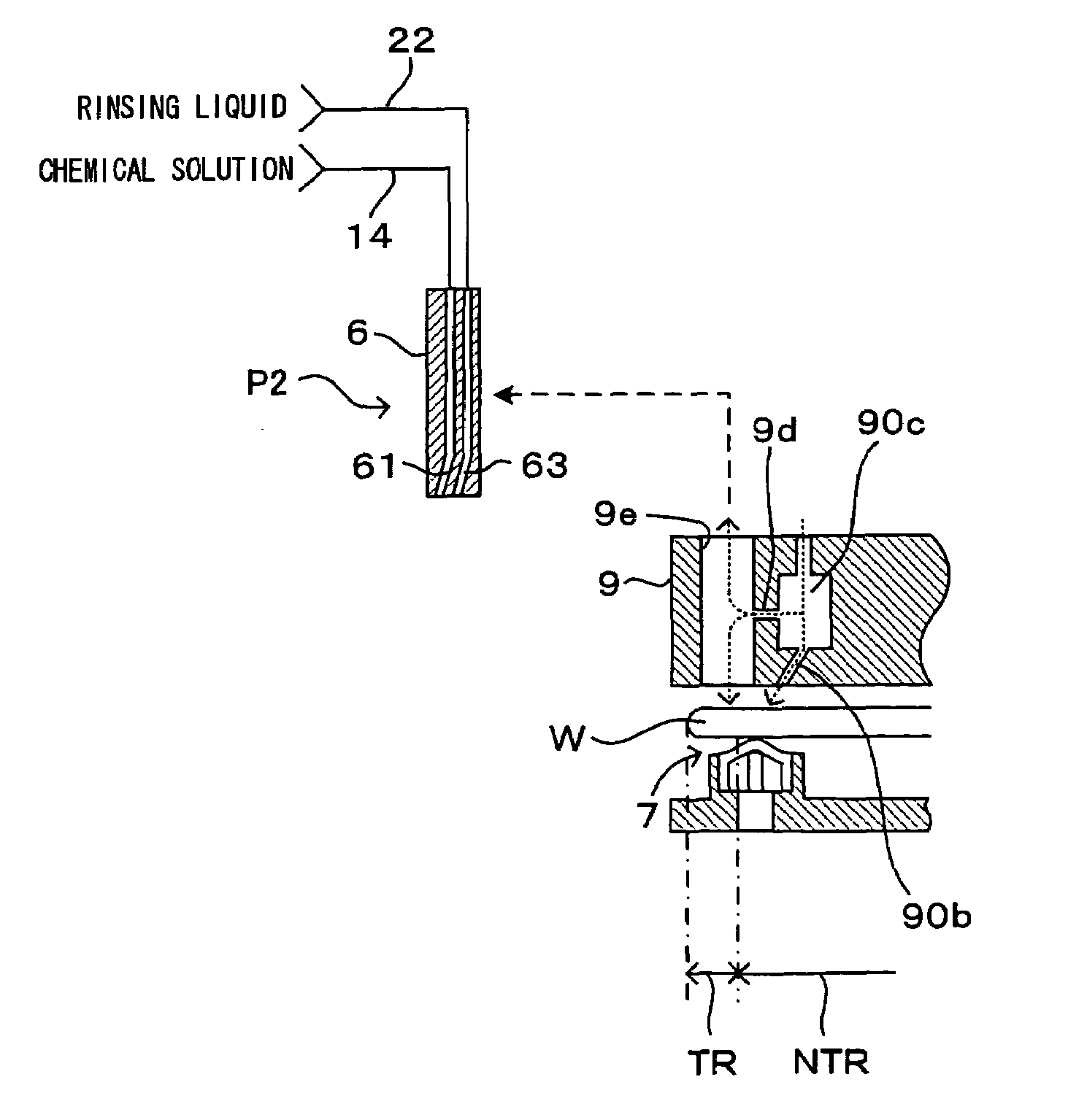
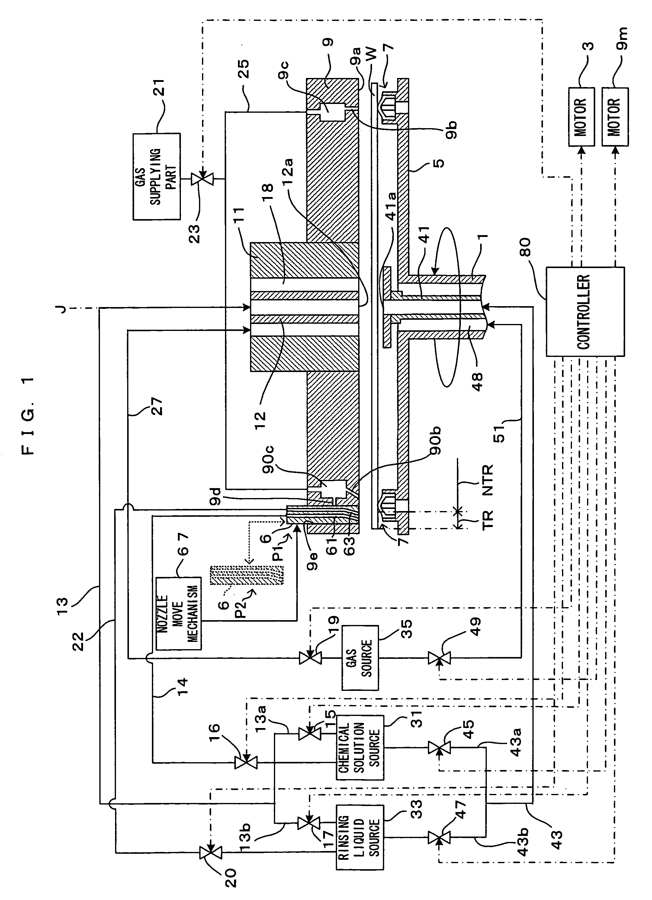
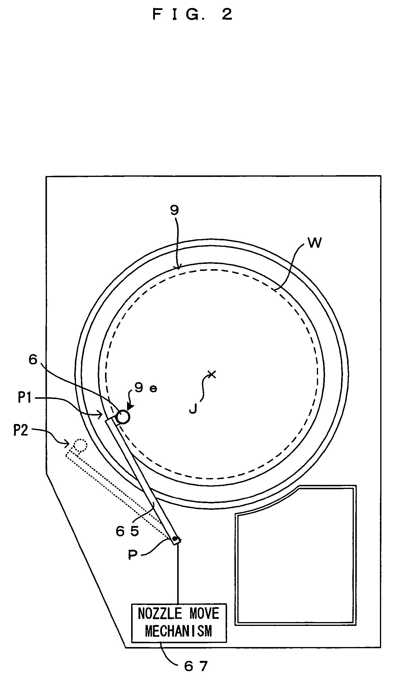
[0022]FIG. 1 is a drawing that shows a first embodiment of a substrate processing apparatus according to the present invention. FIG. 2 is a plan view of the substrate processing apparatus that is shown in FIG. 1. In this substrate processing apparatus, a chemical solution of the chemical substance, an organic solvent or the like is supplied to the surface of a substrate W such as a semiconductor wafer, thereby performing chemical processing. After chemical processing, a rinsing liquid such as pure water and DIW is supplied to the surface of the substrate W to rinse. In this specification, the chemical solution and the rinsing liquid are hereinafter also referred to as “processing liquid(s)”, as necessary. Spin drying is executed after rinsing of the substrate W. In this substrate processing apparatus, the aforementioned processing can be executed by supplying the processing liquid to the bottom surface of the substrate W. The aforementioned processing can also be executed by supplyi...


PUM

PropertyMeasurementUnit
distanceaaaaaaaaaa
distancesaaaaaaaaaa
sizeaaaaaaaaaa

Abstract

On the top surface of a substrate, an atmosphere blocker plate, of which plan size is equal or larger than the substrate size, is disposed opposing to the top surface of the substrate. In the rim portion of the atmosphere blocker plate, a vertical through hole is formed so that a nozzle can be inserted into the hole. Nozzle move mechanism moves the nozzle to insert the nozzle to the through hole and position it to the opposing position that is opposed to the top rim portion of the substrate and to the retract position that is away from the atmosphere blocker plate. Processing liquid is supplied from the nozzle, which is positioned to the opposing position, to the top rim portion of the substrate.

Description

CROSS REFERENCE TO RELATED APPLICATION[0001]The disclosure of Japanese Patent Application No. 2004-223412 filed Jul. 30, 2004 including specification, drawings and claims is incorporated herein by reference in its entirety.BACKGROUND OF THE INVENTION[0002]1. Field of the Invention[0003]The invention relates to a substrate processing apparatus for performing processing such as cleaning of various types of substrates such as semiconductor wafers, glass substrates for photo mask, glass substrates for liquid crystal display, glass substrates for plasma display and optical disk substrates by supplying a processing liquid to these substrates.[0004]2. Description of the Relates Art[0005]In the manufacturing process for semi conductor devices, coating of a thin metallic film such as a thin copper film is often performed on the entire top surface and edge surface (and bottom surface in some cases) of a substrate. Then, the metallic thin film is removed by etching from the portions where coat...

Claims


Application Information

Patent Timeline
Patent Type & Authority Patents(United States)
IPC IPC(8): B08B3/00H01L21/306
CPCB08B3/04H01L21/6708H01L21/67051C03C23/0075
Inventor MIYA, KATSUHIKO
Owner DAINIPPON SCREEN MTG CO LTD
Why Eureka
Try Eureka