Image display apparatus having deformation detection
a technology of deformation detection and display apparatus, which is applied in the direction of instruments, computing, electric discharge tubes, etc., can solve the problems of distortion or color deviation, difference, etc., and achieve the effect of reducing strain
- Summary
- Abstract
- Description
- Claims
- Application Information
AI Technical Summary
Benefits of technology
Problems solved by technology
Method used
Image

Examples
first embodiment
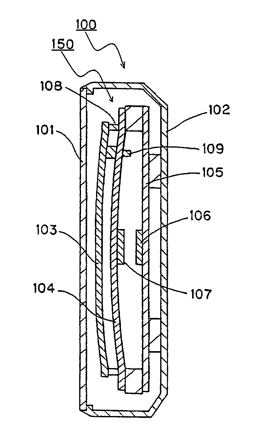
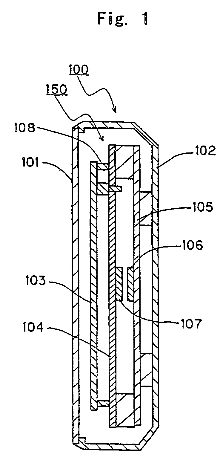
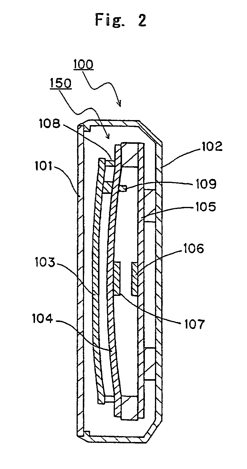
[0024]FIG. 1 is a cross-sectional view of an image display unit when not displaying an image in accordance with a first embodiment. In the situation illustrated in FIG. 1, the power supply is not turned on FIG. 2 is a cross-sectional view of the image display unit when displaying a high-tone (high-luminance) image in accordance with the first embodiment. In the situation illustrated in FIG. 2, the power supply is turned on, a high-tone image is input, and high power is supplied to the face plate. FIG. 3 is a circuit block diagram of the image display apparatus in accordance with the first embodiment.
[0025]The image display apparatus A in accordance with this embodiment includes an image display unit 100, a control unit 1201 (see FIG. 3) that drives a display panel 150, and a detecting unit 1202 (see FIG. 3) that detects strain of the display panel.
[0026]The image display unit 100 includes the display panel 150 that displays an image by irradiating a fluorescent material with electro...
second embodiment
[0068]FIG. 8 is a cross-sectional view of an image display unit in accordance with a second embodiment of the present invention.
[0069]An image display unit 200 in accordance with the second embodiment includes a display panel 250 that displays an image by irradiating a fluorescent material with electrons emitted from an electron emitter element, a front protection plate 201 that protects the display panel 250 from the outside, and a housing 202. The front protection plate 201 is disposed to face the display side of the display panel 250 at a distance.
[0070]The display panel 250 forms a vacuum container with a face plate 203, a rear plate 204, and a frame member 208. The display panel 250 includes a first transparent electrode 206 that is disposed in a visible region on the side facing the front protection plate 201, and a second transparent electrode 207 that is disposed on the front protection plate 201 facing the first transparent electrode 206. Here, the “visible region” is the r...
third embodiment
[0081]FIG. 9 is a cross-sectional view of an image display unit in accordance with a third embodiment of the present invention.
[0082]An image display unit 300 in accordance with the third embodiment includes a display panel 350 that displays an image by irradiating a fluorescent material with electrons emitted from an electron emitter element, a front protection plate 301 that protects the display panel 350 from the outside, and a housing 302.
[0083]The display panel 350 forms a vacuum container with a face plate 303, a rear plate 304, and a frame member 308. In this embodiment, a strain gauge sensor 306 is attached on the back side of the rear plate 304 of the display panel 350.
[0084]In this embodiment, the power difference between the face plate 303 and the rear plate 304 is not large with a low-tone (low-luminance) image, as in the first and second embodiments. However, with a high-tone (high-luminance) image, the power difference becomes large, and convex deformation toward the f...
PUM
 Abstract
Description
Claims
Application Information